

Wifi
Wi-Fi is one of the key technologies of modern wireless communication that allows devices to exchange data without cables using radio waves. From smartphones and laptops to microcontrollers and Internet of Things devices, Wi-Fi provides convenient network connectivity, fast data exchange, and remote control. In this article, we will cover the basic principles of how Wi-Fi works, its modes, IP addressing, and the TCP and UDP transport protocols to understand how this technology is used in practice, including on STM32 microcontrollers.
A Wi-Fi signal is transmitted by an access point in all directions, similar in principle to light from a lamp. Unlike light, however, radio waves can pass through walls and various obstacles, although their strength gradually decreases. As the signal passes through different materials, it is attenuated differently: wood and drywall barely interfere with propagation, while concrete, metal, and even water significantly degrade reception.
Wi-Fi operates in the unlicensed radio-frequency spectrum, which is divided into several bands:
2.4 GHz
The most common Wi-Fi band.
- Long signal range (penetrates walls better).
- Lower speed compared to 5 GHz.
- Often crowded, as it is also used by Bluetooth, microwaves, and other devices.
- Channels: 1–14 (allowed channels vary by country).
5 GHz
- Higher speed with less interference.
- Shorter range; signal does not penetrate walls as well.
- Channels: around 20–25, depending on the country (U-NII bands).
- Commonly used for video streaming, gaming, and office Wi-Fi.
6 GHz
- New frequency band for Wi-Fi 6/6E.
- Very high speed with minimal interference.
- Limited range; signal poorly penetrates walls.
A few words about channels. A Wi-Fi channel is a portion of the radio frequency band used for data transmission. For example, the 2.4 GHz band includes channels like 2412, 2417, 2422 MHz, and so on, with a 5 MHz spacing. Non-overlapping channels help ensure stable and reliable operation.
Wi-Fi Standards
A Wi-Fi standard is a set of technical rules that define how devices communicate over a wireless network: which frequencies to use, the data transmission speeds, how to encode the signal, and how to ensure compatibility between different devices.
The main Wi-Fi standards are:
802.11b
- Frequency: 2.4 GHz
- Speed: up to 11 Mbps
- Rarely used today.
802.11g
- Frequency: 2.4 GHz
- Speed: up to 54 Mbps
- Was the main standard for a long time.
802.11n (Wi-Fi 4)
- Frequencies: 2.4 and 5 GHz
- Speed: up to 600 Mbps
- Supports MIMO (multiple antennas)
- Still widely used.
802.11ac (Wi-Fi 5)
- Frequency: 5 GHz
- Speed: up to several Gbps
- Wider channels (80–160 MHz)
- Ideal for high-speed applications.
802.11ax (Wi-Fi 6 / 6E)
- Frequencies: 2.4 / 5 / 6 GHz
- Better performance with many devices
- Lower latency and higher efficiency
In microcontroller and IoT devices, Wi-Fi standards 802.11b/g/n operating in the 2.4 GHz band are usually used. These standards provide sufficient speed, good range, and low power consumption, which are far more important for embedded systems than the gigabit speeds of modern Wi-Fi 5 and Wi-Fi 6.
Router
Let’s clarify what a router is. A router is the central node of a network that connects devices to each other and to the Internet. It’s important to understand that a router creates a network by acting as an access point that devices connect to. It also assigns addresses so that devices can communicate, directs data packets to their destinations, and provides protection for your network.
Practical Implementation
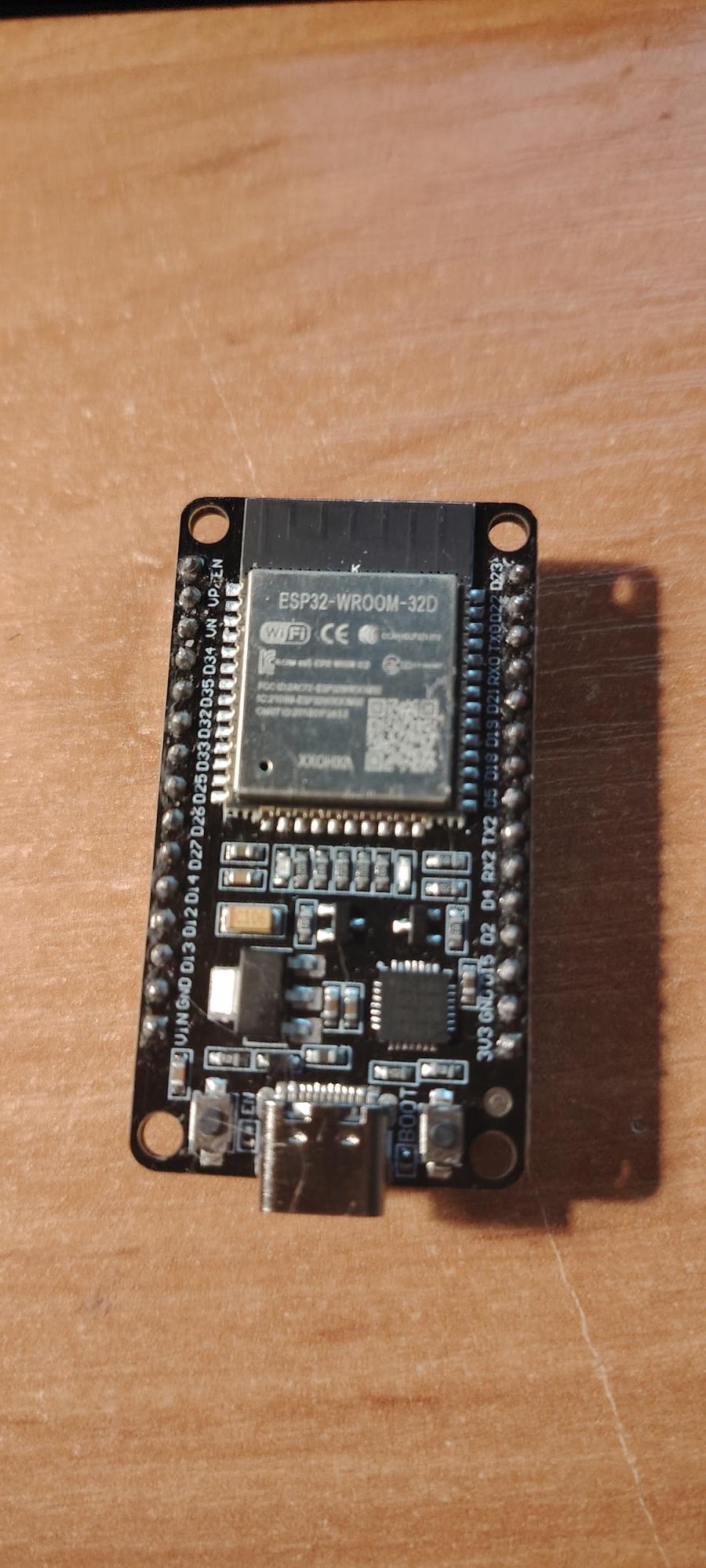
In this example, we will create a simple web interface to control the microcontroller’s pins over Wi-Fi. We will connect an ESP32 WROOM board to an existing wireless network in client mode (STA), obtain an IP address from the router, and run an HTTP server on the standard port 80. After that, the device can be accessed from a browser using its IP address, opening a web page generated by the microcontroller itself. The page contains control elements that send HTTP requests to the ESP32 WROOM. Based on the received request, the device turns an LED on or off, demonstrating how Wi-Fi can be used to remotely control the hardware of a microcontroller through a standard web browser.
The board looks like this:
We will use the Arduino IDE and set it up to work with our board. To do this, Arduino IDE needs Espressif board support installed via the Boards Manager.
- Go to File – Preferences and in the Additional Board Manager URLs field, add:
https://raw.githubusercontent.com/espressif/arduino-esp32/gh-pages/package_esp32_index.json - Then go to Tools – Board – Boards Manager and install esp32 by Espressif Systems.
- After that, select your module:
Tools – Board – ESP32 Arduino – ESP32 Dev Module
The firmware code is as follows:
#include <WiFi.h>
#include <WebServer.h>

const char* ssid = "";        // Wi-Fi network name
const char* password = "";  // Password

WebServer server(80); // Web server on port 80
const int ledPin = 2; // GPIO of built-in led

// Main page

void handleRoot() {
    String html = "<h1>ESP32 Web LED Control</h1>";
    html += "<p><a href=\"/on\">EN LED</a></p>";
    html += "<p><a href=\"/off\">DES LED</a></p>";
    server.send(200, "text/html", html);
}
// Turn on the LED
void handleOn() {
    digitalWrite(ledPin, HIGH);
    server.sendHeader("Location", "/");
    server.send(303); // Redirect to the main page
}

// Turn off the LED
void handleOff() {
    digitalWrite(ledPin, LOW);
    server.sendHeader("Location", "/");
    server.send(303);
}

void setup() {
    pinMode(ledPin, OUTPUT);
    digitalWrite(ledPin, LOW);

    Serial.begin(115200);
    WiFi.begin(ssid, password);

    Serial.print("Connect to Wi-Fi");
    while (WiFi.status() != WL_CONNECTED) {
        delay(500);
        Serial.print(".");
    }
Serial.println("\nConnected!");
    Serial.print("IP-адрес ESP32: ");
    Serial.println(WiFi.localIP());

    server.on("/", handleRoot);
    server.on("/on", handleOn);
    server.on("/off", handleOff);
    server.begin();
}

void loop() {
    server.handleClient(); // Handle incoming requests
}
After that, the web interface will be accessible at the IP address assigned to the ESP32 WROOM by your router for example, http://192.168.100.3.
This example is as simple and reliable as possible because the Arduino environment for ESP32 already includes a complete Wi-Fi stack and a web server library handling of the network, TCP/IP, and HTTP is all managed by the libraries. The developer only needs to define the logic for processing requests.
Additionally, the ESP32 WROOM board itself is a complete solution with built-in Wi-Fi. However, in real embedded projects, a separate Wi-Fi module is often used, connected to an external microcontroller. Let’s look at one such module using the ESP-12F as an example.
ESP-12F
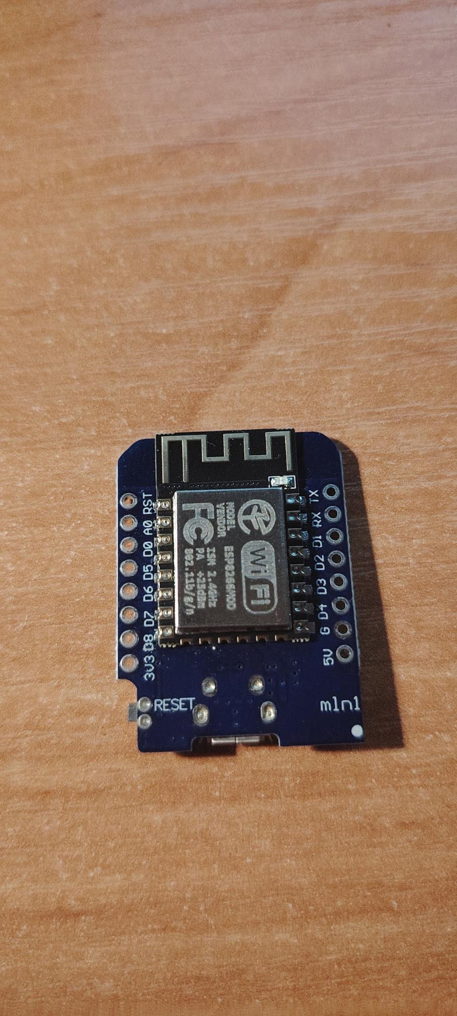
We actually have an ESP-12F module. It looks like this:
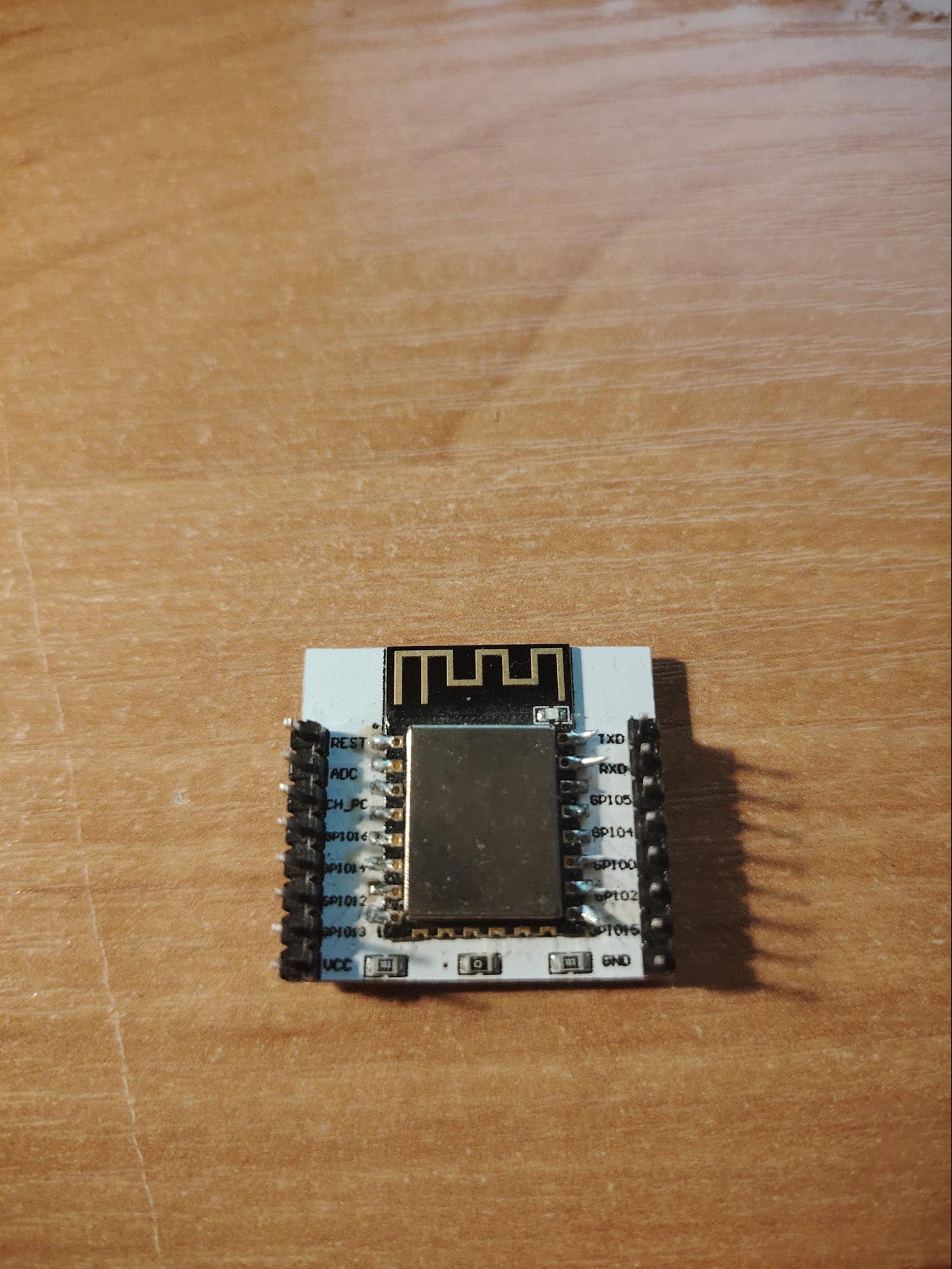
The ESP-12F is a Wi-Fi module based on the ESP8266EX microcontroller, which already integrates the processor, memory, radio components, and a full TCP/IP stack. Unlike standard radio modules, the ESP-12F can independently handle network protocols: it can connect to access points, obtain an IP address via DHCP, establish TCP connections, and exchange data over HTTP. Because of this, the module is often used as a network coprocessor for STM32 microcontrollers, providing Wi-Fi support without the need to implement complex network logic on the main microcontroller.
ESP-12F Specifications
- Microcontroller: ESP8266EX, up to 80 MHz
- Flash memory: 4 MB
- RAM: 80 KB (SRAM)
- Operating voltage: 3.3 V DC
- Current consumption: up to 215–240 mA (during transmission), down to 10 µA (deep sleep)
- GPIO: 11–13 general-purpose pins, including PWM, I2C, SPI, UART
- ADC: 1 input (10-bit, 0–1 V)
- Dimensions: 24 × 16 × 3 mm
- Antenna: Built-in PCB antenna
Pinout
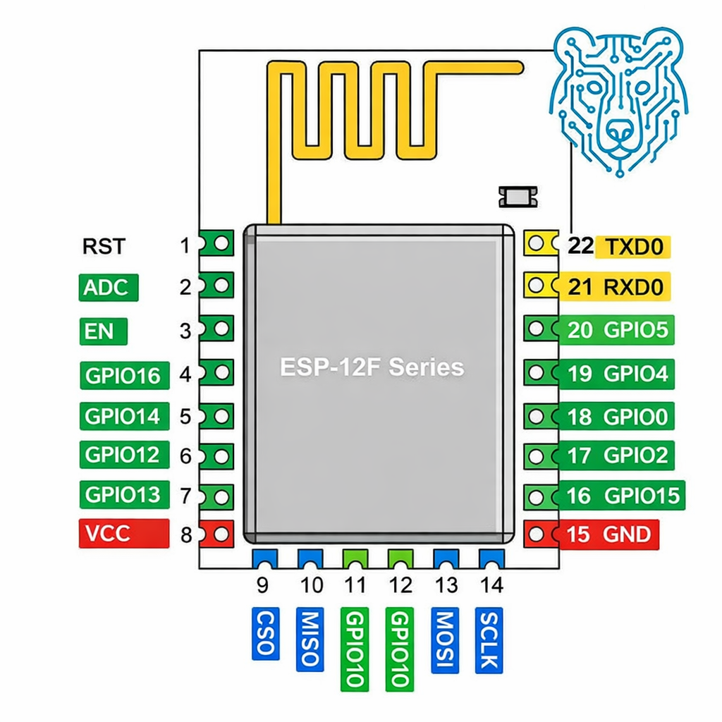
The ESP-12F pinout defines how the module connects to power and to an external microcontroller. In addition to the 3.3 V and GND power lines, the control pins EN and RST play an important role, managing the module’s power-on and reset functions. Data exchange with the main controller is carried out via the UART interface, using the TXD0 and RXD0 pins.
The module also provides general-purpose GPIO pins, which can be used to control peripherals, read signals, or set the boot mode. Special attention should be given to GPIO0, GPIO2, and GPIO15: their states at startup determine whether the ESP-12F boots normally or enters programming mode. Correct understanding of the pinout is therefore essential for reliable operation of the Wi-Fi module within a device.
Flashing and Main Operating Concept of the Module
The ESP-12F can be used in two ways. In the first case, the module functions as a standalone microcontroller: a program is uploaded to it, and it independently controls its pins and network connection. In the second case, the ESP-12F is used as a Wi-Fi coprocessor for an STM32. Here, the main code runs on the STM32, while the ESP receives AT commands via UART and handles all Wi-Fi and TCP/IP stack operations. This approach allows wireless connectivity to be added to microcontroller projects without implementing network protocols manually.
We will flash our ESP-12F so it can be used as a standalone module. For this, we will use an Arduino UNO and the Arduino IDE development environment.
ESP-12F Connection Diagram
The module can operate in two modes: programming mode and normal code execution mode. For programming mode, the connection diagram is as follows:
Programming Mode
ESP12f
VCC – 3.3V
GND – GND
TX – UART TX ArduinoUNO
RX – UART RX ArduinoUNO
EN – resistor 10 kiloohms -3.3V
GPIO0 – resistor 10 kiloohms – GND
GPIO2 – resistor 10 kiloohms – 3.3V
GPIO15 – resistor 10 kiloohms – GND
RST – resistor 10 kiloohms – 3.3V
RST – button – GND
VCC – 100 µF – GND
Let’s go step by step. It’s best to power the module from a separate power supply, as the module itself can draw significant currents of up to 500 mA.
For UART connections with an Arduino, connect TX to TX and RX to RX, but pass RX through a voltage divider. The diagram is as follows:
RX(Arduino) – 1КОМ – RX(ESP12f) – 2КОМ – GND
This part should be clear and does not change during flashing just make sure not to forget the resistors.
EN – resistor 10 kiloohms -3.3V
GPIO0 – resistor 10 kiloohms – GND
GPIO2 – resistor 110 kiloohms – 3.3V
GPIO15 – resistor 10 kiloohms – GND
A very important pin is RST. RST is the hardware reset input of the microcontroller. In normal operation, it should be held at 3.3 V, so it is pulled up to power with a resistor to prevent the pin from floating and causing false resets.
When we briefly connect RST to GND using a button, a logic low appears on the input, and the chip fully restarts: it stops execution, resets registers, reads the boot pins (GPIO0, GPIO2, GPIO15) again, and starts the program from the beginning. Accordingly, we connect it through a resistor in normal operation and in parallel use a button to pull it to GND. Press the button — the microcontroller resets.
A capacitor is also required for stable module operation. I used a 100 µF electrolytic capacitor, and the circuit works perfectly.
Operating Mode
To switch to normal operating mode, pull the GPIO0 pin up to 3.3 V through a resistor and press the RST button. This will bring the microcontroller into its normal working mode.
IDE Settings for Flashing
As mentioned earlier, we use the Arduino IDE to flash our ESP-12F module. The Arduino IDE already includes a ready-made core for ESP, which automatically handles compilation, memory management, and the bootloader so there’s no need to manually configure the toolchain or flash parameters.
Step by step:
- Open File – Preferences and in the Additional Boards Manager URLs field, add:
https://arduino.esp8266.com/stable/package_esp8266com_index.json
This tells the IDE where to find the ESP8266 platform description, including the compiler, bootloader, libraries, memory settings, clock frequencies, and flashing tools. - Open Tools – Board – Boards Manager, find the package ESP8266 by ESP8266 Community, and install it.
- Next, select the board Generic ESP8266 Module and configure the following settings.
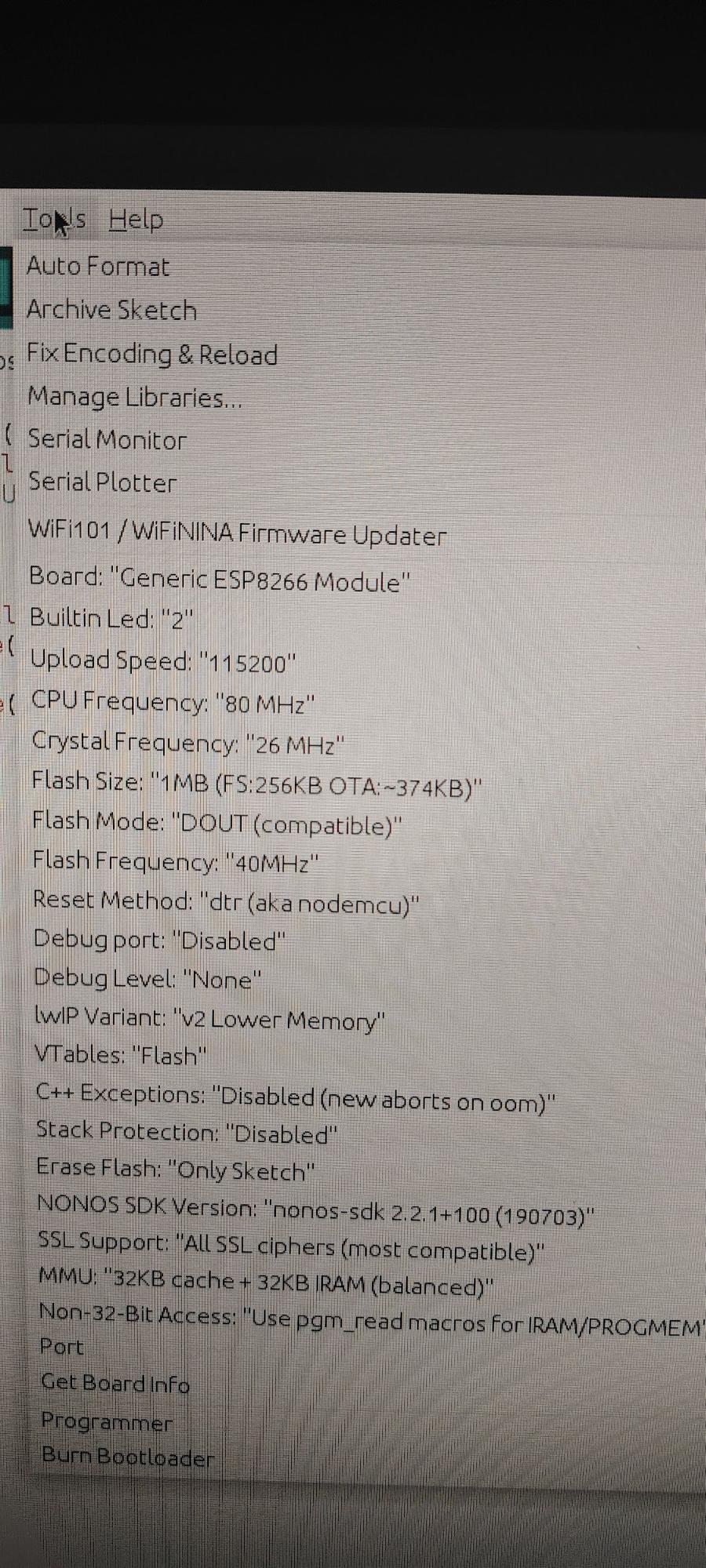
Pay attention to the Flash Mode setting. It only worked for me when I selected DOUT.
Firmware Code.
Let’s upload a test firmware to our ESP-12F.
void setup() {
Serial.begin(115200);
Serial.println("SETUP OK");
pinMode(2, OUTPUT);
}

void loop() {
Serial.println("LOOP");
digitalWrite(2, LOW);
delay(500);
digitalWrite(2, HIGH);
delay(500);
}
All it does is send the message “SETUP OK” to the serial monitor and then blink the LED on the board. The LED is connected to GPIO2 and will blink every half second.
Next, let’s look at another popular option for working with Wi-Fi: the WEMOS module.
WEMOS Module . Specifications
Let’s set a more practical task. Since we already know how to work with the ESP32-WROOM, we can use it as an AP (access point). Here, we’ll create a small web interface that displays the value of a variable. A second WEMOS module based on the ESP8266 will act in STA (client) mode. It will connect to our AP module and periodically send the variable’s value, which we will see updated on the web interface.
A brief overview of the WEMOS module:
- Popular series of boards based on ESP8266 / ESP32
- Wi-Fi: 2.4 GHz (802.11 b/g/n)
- CPU frequency: 80 / 160 MHz
- Flash memory: typically 4 MB
- Logic level: 3.3 V
- Power: 5 V via USB or 3.3 V directly
- GPIO: about 11 pins
- Interfaces: UART, SPI, I2C, PWM, ADC
Flashing is done via USB, which is very convenient. It’s important to remember not to apply 5 V to the pins, only 3.3 V. Programming can be done directly from the Arduino IDE.
Let’s start with the ESP32-WROOM. The full firmware code is below.
#include <WiFi.h>
#include <WebServer.h>
const char* ssid = "ESP32_AP";
const char* password = "12345678";
WebServer server(80);
WiFiServer tcpServer(5000); // TCP Server for WeMOS
const int ledPin = 4;
unsigned long lastPrint = 0;
volatile int counter = 0; // The variable that will be updated by the WEMOS.
//wep-page
void handleRoot(){
String html = "<h1>ESP32 Web LED Control (AP Mode)</h1>";
html += "<p><a href='/on'>Turn ON LED</a></p>";
html += "<p><a href='/off'>Turn OFF LED</a></p>";
html += "<p>Counter value: " + String(counter) + "</p>"; // Variable output
server.send(200,"text/html",html);
}


//LED control
void handleOn(){
digitalWrite(ledPin,HIGH);
server.sendHeader("Location","/");
server.send(303);
}

void handleOff(){
digitalWrite(ledPin,LOW);
server.sendHeader("Location","/");
server.send(303);
}

void setup(){
pinMode(ledPin,OUTPUT);
digitalWrite(ledPin,LOW);
Serial.begin(115200);

// Access point
WiFi.softAP(ssid,password);
Serial.println("Access Point started");
Serial.print("IP address: ");
Serial.println(WiFi.softAPIP());


// web-server
server.on("/", handleRoot);
server.on("/on", handleOn);
server.on("/off", handleOff);
server.begin();
// TCP server for receiving data
tcpServer.begin();
tcpServer.setNoDelay(true); //disable buffering
Serial.println("TCP server started on port 5000");
}

void loop(){
server.handleClient();


// TCP data reception
WiFiClient client = tcpServer.available();
if(client){
Serial.println("New client connected");
String msg = "";
while(client.connected() && client.available()){
char c = client.read();
if(c == '\n') break; // end of line
msg += c;
}
if(msg.length() > 0){
counter = msg.toInt(); // update the variable
Serial.print("Received counter: ");
Serial.println(counter);
}
client.stop();
Serial.println("Client disconnected");
}
// Print the number of clients every 3 seconds
if(millis()-lastPrint > 3000){
lastPrint = millis();
int n = WiFi.softAPgetStationNum();
Serial.print("Connected clients: ");
Serial.println(n);
}


delay(10);
}
It does four things:
- Starts the server
- Creates the web interface
- Sets up the access point
- Displays our variable and the number of connections
Next is the firmware code for the WEMOS module.
#include <ESP8266WiFi.h>
#include <WiFiClient.h>
const char* ssid = "ESP32_AP"; // Wi-Fi ESP32
const char* password = "12345678";
const char* host = "192.168.4.1"; // IP ESP32
const uint16_t port = 5000; // TCP port ESP32
unsigned long lastSend = 0;
int counter = 0;
WiFiClient client;
void setup(){
Serial.begin(115200);
delay(500);
WiFi.mode(WIFI_STA);
WiFi.begin(ssid,password);
Serial.print("Connecting");
while(WiFi.status() != WL_CONNECTED){
delay(500);
Serial.print(".");
}
Serial.println();
Serial.println("Connected to ESP32 AP");
Serial.print("IP: ");
Serial.println(WiFi.localIP());
}

void loop(){
// Every 3 seconds, increment and send the counter
if(millis() - lastSend >= 3000){
lastSend = millis();
counter++;
if(!client.connected()){
Serial.println("Connecting to server...");
if(!client.connect(host, port)){
Serial.println("Connection failed");
return;
}
Serial.println("Connected!");
}

// sending counter
String msg = String(counter);
client.println(msg);
Serial.print("Sent: ");
Serial.println(msg);
}
}
Basically, it connects to the address 192.168.4.1 and then, every 3 seconds, increments the variable and sends this data over Wi-Fi. To see the result, you can connect to the Wi-Fi from your device, for example, a phone, and open the web interface at http://192.168.4.1.
In this topic, we explored what Wi-Fi is in the context of embedded systems: how a microcontroller can be more than just the “brain” of a device, becoming a full-fledged network participant. We looked at how Wi-Fi works, the different modes (STA, AP, AP+STA), and the difference between connecting to a router and creating your own access point.
We also examined popular modules and boards ESP8266, WEMOS, ESP32-WROOM and saw that today Wi-Fi is often built directly into the microcontroller. This makes it possible to control devices via a browser, phone, server, or cloud without additional hardware.
The main idea is that Wi-Fi turns ordinary electronics into networked devices. A relay, robot, sensor, or LED with Wi-Fi becomes part of a system, allowing remote configuration, monitoring, and automation. Understanding how Wi-Fi works and which modules are available provides a foundation for creating modern IoT projects from simple web panels to complex networked robots and smart homes.