

RS485
Let’s talk about RS485. What is RS485? It’s a physical layer standard. And this is where many people get confused. Surprisingly, they often mix up RS485 with communication protocols like UART, I2C, or SPI. This confusion happens for a very simple reason: you take two devices and connect them together. You use UART, send data back and forth, and everything works. So, you might ask, why do we even need RS485 if it already works? The thing is, it only works in ideal lab conditions. Try connecting two devices in an industrial workshop with motors, magnetic fields, and interference over a distance of even 100 meters. You won’t succeed. And if you do, the connection will be extremely unreliable. That’s why we need a physical layer protocol like RS485 , it works over long distances, reliably, and quickly.
Principle of Operation and General Setup
RS-485 operates as a common differential bus. All nodes are connected in series to the A and B lines, sharing the same physical channel. Communication is half-duplex: at any given time, only one transmitter is active while the others are in receive mode.
The controller manages the transmission direction via the transceiver’s DE/RE pins, enabling the transmitter only while sending data. After transmission, the line is released, allowing other nodes to respond.
For a network consisting of a controller and multiple nodes, each device requires an RS-485 transceiver, twisted pair for the A/B lines, a common GND, 120 Ω terminators at the ends of the line, and proper bus topology without star connections. The data rate is chosen based on line length, typically not exceeding a few hundred kilobits per second.
The general setup (without repeaters) looks like this:
MCU → RS-485 Transceiver → A/B → Bus → A/B → RS-485 Transceiver → MCU UART
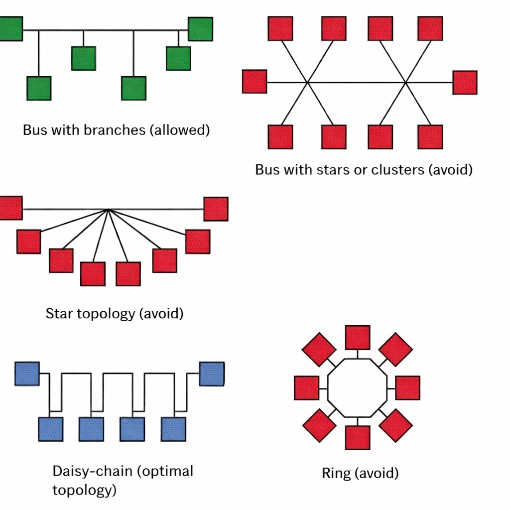
Topology
If a network operates at low data rates, with relatively slow signal edges and short cable segments, topology is not critical. However, as the line length increases, data rates rise, or interference appears, topology becomes crucial. In such cases, the only simple and reliable way to control signal reflections is a daisy-chain connection, where devices are connected sequentially along the line.
This doesn’t mean RS-485 cannot be used in a star configuration. However, in a star setup, managing reflections and interference becomes more of an art than a predictable engineering task. That’s why, in practice, a sequential bus topology (daisy-chain) is almost always chosen for stable operation.
Key Characteristics of RS485
- Range: Up to 1200 meters
- Speed: Up to 10 Mbps on short lines; on long lines, it may drop to 1 Mbps or even lower
- Bus capacity: Up to 32 devices on a single bus without repeaters. Special transceivers can be used to significantly increase the number of nodes.
- Half-duplex: The A/B lines are used for both transmitting and receiving, but only one node can transmit at a time. For full duplex, use 4 wires.
- Voltage levels: TTL-compatible input (3 V or 5 V). Differential voltage between transceivers typically ranges from 0.2 V to 2 V.
Grounding and Termination
Although RS-485 transmits data over the differential A/B pair, in real systems devices are often located far apart and can have different ground potentials. Due to cable length, interference, leakage currents, and the operation of heavy equipment, the voltage difference between the grounds of nodes can reach several volts.
RS-485 transceivers can tolerate only a limited range of such common-mode voltage. If the potential difference becomes too large, the receiver may operate unreliably or even fail. In practice, a third wire—a common GND—is often added to equalize device potentials.
In more complex or industrially noisy environments, galvanic isolation of RS-485 or shielded cables with proper grounding are used. This improves communication reliability and protects equipment from ground currents and interference.
Over long distances, an RS-485 line behaves not just as a “wire” but as a transmission line with characteristic impedance. When the transmitter generates a signal edge, an electromagnetic wave propagates along the cable. If the line’s termination is not matched, part of the signal reflects back.
These reflections superimpose on the main signal, distorting voltage levels and edges, causing false transitions and reception errors, especially at high speeds and long distances. As a result, the receiver may see “extra bits,” jittery edges, or unstable levels.
A terminator is a resistor (typically around 120 Ω) connected between the A and B lines at the ends of the bus. It matches the cable impedance to the load and absorbs the wave, preventing reflections. This ensures the signal reaches the receiver cleanly, without echo or distortion.
It’s important to place terminators only at the physical ends of the line, not at every node. Placing them everywhere would overload the bus, making it difficult for the transmitter to maintain proper signal levels.
MAX485
In our setup, we’ll be using the MAX485 transceiver, so a few words about it.
The MAX485 is an IC that allows two devices to exchange data over a single twisted pair over long distances. It can transmit and receive signals, but not at the same time (half-duplex). When the microcontroller wants to send data, the MAX485 enables the transmit line; when it needs to receive, it disables transmission and enables reception. This makes communication robust against interference and allows data exchange using just two wires.
The MAX485 works on the principle of differential signaling. Instead of simply sending a high or low voltage relative to ground, the chip creates a voltage difference between the A and B lines. For example, a logical “1” occurs when A is a few volts higher than B, and a logical “0” when B is higher than A. The receiver reads the difference between A and B, not the absolute voltage relative to ground, making the signal almost immune to external noise and interference over long cables. In other words, even if both lines pick up some noise, the key is the voltage difference between them, and the data is received correctly.
MAX485 Pinout
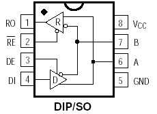
MAX485 Pinout
- RO (Receiver Output): Data output during reception
- RE (Receiver Enable): Enables/disables the receiver
- DE (Driver Enable): Enables/disables the transmitter
- DI (Driver Input): Data input for transmission
- VCC: Power supply +5 V
- A, B: Differential data lines
- GND: Ground
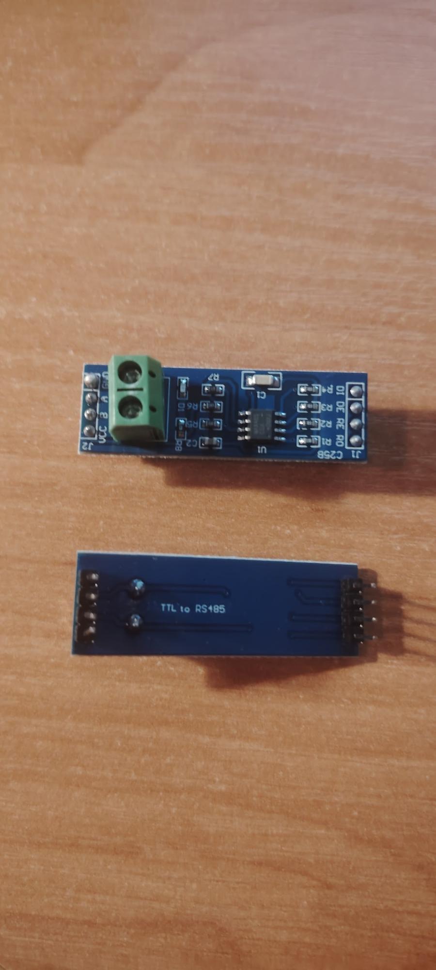
This is what the module looks like.
Practical Implementation
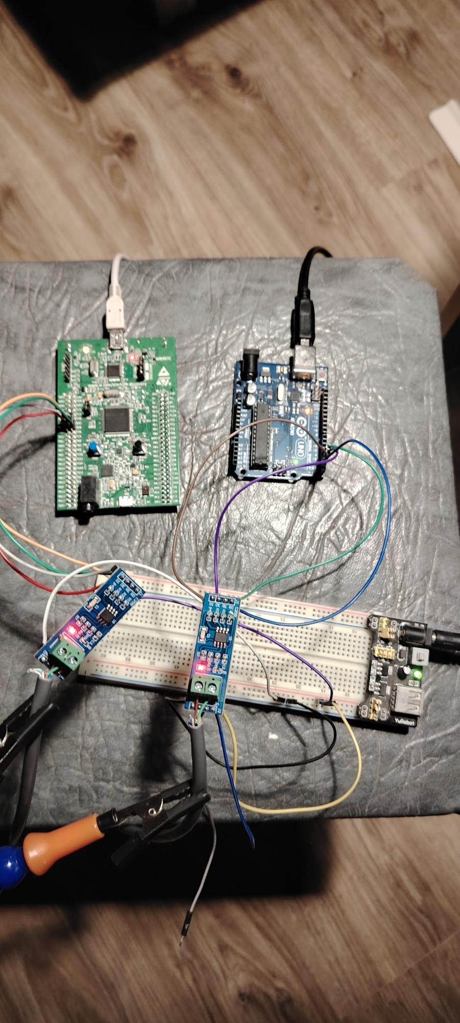
Theory is good, but let’s get hands-on with this interface. We’ll transmit data from an STM32F4 Discovery to an Arduino UNO via UART using the RS485 interface. The distance will be just a couple of meters, but that’s enough for learning purposes.
For this, you’ll need: STM32F4 Discovery, Arduino UNO, a MAX485 module, and a twisted-pair cable. Don’t forget the termination resistors at the ends of the line — in our case, they are already on the MAX485 module.
The operation logic will be as follows:
STM32:
- Initialize UART
- Prepare for transmission:
- DE = 1 (Driver Enable → enable the transmitter)
- RE = 1 (Receiver Enable → disable reception, since RE is active low)
- Send a string over UART
- Return to receive mode
Connection Diagram
The MAX485 module has data lines (RO, DI) and control lines (DE, RE). For our data transmission, the wiring will be as follows:
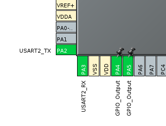
STM32 → MAX485
- PA2 (UART TX) → DI
- PA3 (UART RX) → RO
- PA4 (output) → DE
- PA5 (output) → RE
Arduino → MAX485
- RO → D0 (RX)
- DI → D1 (TX)
- 2 → DE
- 3 → RE
Power: VCC from 3–5 V (we’ll use 5 V)
Ground: common GND
This is how the setup looks.
Software Code
Let’s start with the STM32F407VGT6.
Since we’re using CubeIDE, we’ll configure the settings there. We need to initialize the UART with the following parameters:
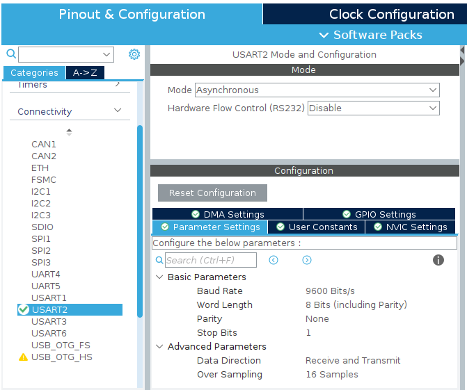
The most important parameter here is the baud rate — both devices must use the same speed.
Next, we configure pins PA4 and PA5 as outputs. The setup will look like this:
I also configured PD12 as an output. This is the LED on the Discovery board, which will visually indicate when a data packet has been sent.
Click the Build button in CubeIDE. Now, let’s add the string we want to transmit.
/* USER CODE BEGIN PV /
uint8_t tx_msg[] = "Hello RS485\r\n";
/ USER CODE END PV */
Next, set PA4 high to put the transceiver into transmit mode. Then, send our string and, for visual feedback, toggle the LED. Finally, insert a 1-second delay.
/* USER CODE BEGIN WHILE */
while (1)
{
HAL_GPIO_WritePin(GPIOA, GPIO_PIN_4, GPIO_PIN_SET);
HAL_UART_Transmit(huart2, (uint8_t)tx_msg, strlen(tx_msg), HAL_MAX_DELAY);
HAL_GPIO_WritePin(GPIOA, GPIO_PIN_4, GPIO_PIN_RESET);
HAL_GPIO_TogglePin(GPIOD, GPIO_PIN_12);
HAL_Delay(1000);
/ USER CODE END WHILE /
/ USER CODE BEGIN 3 */
}
Now for the Arduino code. I’ll post it in full since it’s very simple.
void setup() {
#define DE_PIN 2 // Driver Enable
#define RE_PIN 3 // Receiver Enable
//Initialize serial port at 9600 baud
Serial.begin(9600);
// Set control pins as outputs
pinMode(DE_PIN, OUTPUT);
pinMode(RE_PIN, OUTPUT);
// Wait for serial port to initialize
while (!Serial) {
; //wait for serial connection
}
Serial.println(“Ready to receive data…“);
}
void loop() {
//Check if data is available
if (Serial.available() > 0) {
//Read string until newline or timeout
String receivedString = Serial.readStringUntil(‘\n’);
// Remove extra spaces and carriage returns
receivedString.trim();
//Print the received string
Serial.print(“Received: “);
Serial.println(receivedString);
}
}
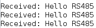
After programming the STM32 and Arduino, power up the entire setup and connect the RS485 line through the MAX485 modules. The STM32 will start transmitting data over UART, the MAX485 converts it to a differential signal, and the Arduino, through its MAX485, receives these bytes. In the Arduino Serial Monitor, you should see the incoming strings sent from the STM32.
In the end, we successfully built the circuit and achieved stable communication over RS485. RS485 is well-suited for industrial applications because it uses differential signaling and is resistant to interference on long lines. This makes the interface reliable even in noisy environments and over long distances.