

Analog-to-Digital Converter.
An Analog-to-Digital Converter (ADC) is a module inside a microcontroller that converts an analog signal (for example, a voltage from a sensor) into a digital value that the microcontroller can process.
A simple example: imagine we have a temperature sensor that outputs a voltage from 0 to 3.3 V. The microcontroller cannot understand analog voltage directly, but with the help of the ADC, it can be converted into a numerical value that the microcontroller can interpret.
Key characteristics of an ADC.
- Resolution (bit depth)
Indicates how many discrete levels the input signal range is divided into.8-bit – 256 levels (0–255)
10-bit – 1024 levels (0–1023)
12-bit – 4096 levels (0–4095)The higher the resolution, the more accurate the measurement. - Input voltage range.An ADC typically operates with an input voltage range from 0 to Vref (for example, 3.3 V or 5 V). Some microcontrollers allow the use of either an internal or an external reference voltage.
- Conversion speed.It is measured in samples per second (SPS). The higher the speed, the faster the microcontroller can read data. However, higher speeds can sometimes reduce accuracy.
ADC Noise.
Noise in an ADC refers to random fluctuations in the measured value even when the input voltage is stable. It can be caused by unstable power supply (Vcc and Vref), interference from the microcontroller’s digital circuitry, external disturbances (long wires, motors, PWM), the ADC’s own thermal noise, and quantization effects.
It is impossible to completely eliminate noise, but it can be reduced:
- Software methods: averaging, median filters, and oversampling.
- Hardware methods: using RC filters on the input, proper power decoupling (capacitors, filters), correct ground layout (separating analog and digital GND), increasing the sampling time, and, if necessary, using buffer amplifiers.
Types of ADCs.
There are several types of ADCs, which differ in their operating principle, speed, and accuracy.
- SAR (Successive Approximation) – the most common type, offering medium speed and accuracy, suitable for most microcontrollers and sensors.
- Sigma-Delta – slow but very accurate, used where small signal changes are important, such as in weight or audio sensors.
- Flash (parallel) – extremely fast but expensive and noisy, used for very high-frequency signals, for example in radio electronics.
The choice of ADC depends on the task: for a standard temperature or voltage sensor, use a SAR ADC; for a highly accurate measurement, use a Sigma-Delta ADC; and for measuring fast real-time signals, use a Flash ADC.
Operating principle
We already know that the resolution of an ADC is the number of discrete levels into which the input voltage is divided. Suppose we have a 10-bit ADC. This means it divides the signal into 1024 steps, which is 2 raised to the power of 10 (2¹⁰ = 1024).
Next, let’s look at the concept of the reference voltage. The reference voltage is the maximum voltage that the ADC can measure. It can be internal, for example 3.3 V, or external, supplied from outside the microcontroller. To measure a higher voltage, a resistor divider is needed to bring the voltage down to the microcontroller’s level. Accordingly, the measured value must be recalculated in code to account for the divider.
The next concept is the quantization step. It is calculated by dividing the reference voltage by the number of levels. For example, 3.3 V / 1024 ≈ 0.0032 V, or 3.2 mV.
Example:
Suppose the ADC input voltage is some value X, not exceeding the reference voltage. For simplicity, let’s say it is 2.5 V. With a reference voltage of 3.3 V, the quantization step is 0.0032 V. Then, 2.5 / 0.0032 ≈ 776. This is the digital value the ADC produces. To convert it back to volts, divide 776 by 1023 and multiply by 3.3, which gives approximately 2.5 V.
Measuring the Voltage of an AA Battery Using an ADC
Now let’s try measuring voltage in practice using an ADC. We have a Discovery board with an STM32F407VGT6 microcontroller. We will use it to measure the voltage of a standard AA battery. First, we’ll do it without DMA to understand the basics, and then we’ll use DMA, as it greatly speeds up operation and frees up the CPU in practice.
Create a new project in CubeIDE. For our example, we will use ADC1, which is located on APB2. In our case, the clock is set to 16 MHz, which is more than enough for this measurement. We select channel IN0 of the ADC.
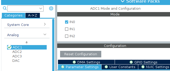
There are a total of 15 such channels, plus additional ones for temperature and calibration measurements, which we won’t cover for now. Let’s go over the settings:
- Mode – Independent, the default setting.
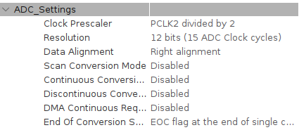
- Clock Prescaler – Divide the clock by 2 to reduce the load on the ADC.
- Resolution – Bit depth. Higher resolution gives more accuracy but slower conversion. We’ll leave it at 12 bits.
The remaining settings will be left at their default values.
Let’s build our project. CubeIDE has created the ADC initialization function MX_ADC1_Init() with the settings we configured. Now, let’s add the code to work with our ADC.
HAL_ADC_Start(&hadc1);//Start the ADC
HAL_ADC_PollForConversion(&hadc1,HAL_MAX_DELAY);//Wait for the conversion to complete
uint32_t adc_value=HAL_ADC_GetValue(&hadc1);//Store the result in a variable
float voltage=(adc_value/4095.0f)*3.3f;//Convert to volts
char buffer[50];//Buffer for the string
int volts=(int)voltage;//Integer part
int cents=(int)((voltage-volts)*100);//Fractional part (2 digits)
int len=sprintf(buffer,"Voltage: %d.%02d V\r\n",volts,cents);//Format the string
HAL_UART_Transmit(&huart3,(uint8_t*)buffer,len,HAL_MAX_DELAY);//Send via UART
HAL_Delay(1000);//Wait 1 second
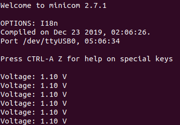
In general, it works like this: we start the ADC conversion and wait for the result. The resulting number is stored in a variable, which we then convert to volts. For clarity, I send this value via UART to a computer and display it in a terminal.
In a real application, it’s necessary to perform averaging to reduce noise and get a more accurate value, but we won’t do that for now. Next, we’ll try doing the same thing using DMA, which is a much better approach.
Measuring Voltage Using an ADC with DMA.
After understanding basic voltage measurement with an ADC, it becomes clear that this approach requires constant CPU involvement: starting the conversion, waiting for the result, and reading the data. This works, but it is inefficient, especially when measurements need to be taken regularly or at high speed.
In such cases, DMA (Direct Memory Access) comes to the rescue. DMA allows data to be transferred directly from the ADC to memory without CPU intervention. In this part of the article, we’ll look at how to set up voltage measurement using an ADC with DMA on the STM32F407VGT6 to make the system more efficient, flexible, and closer to real embedded applications. For this, we use the DMA–ADC–Timer setup.
The general idea is as follows: the ADC performs measurements, and the results are written directly into memory without CPU involvement. Then, on a timer interrupt event, we simply take the accumulated data, process it, average it, and convert it to voltage. Finally, we send it to our terminal via UART.
This way, the CPU doesn’t spend time on each individual measurement but only works with the ready data, making the system more efficient and easier to scale.
Let’s configure the necessary settings in CubeIDE.
Go to the ADC1 tab and add a DMA stream.
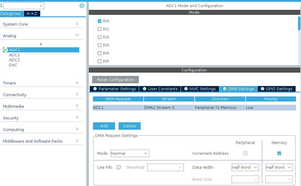
Mode – Normal. Data is transferred from the peripheral to memory.
Important point: be sure to enable Continuous Conversion Mode and DMA Continuous Requests.
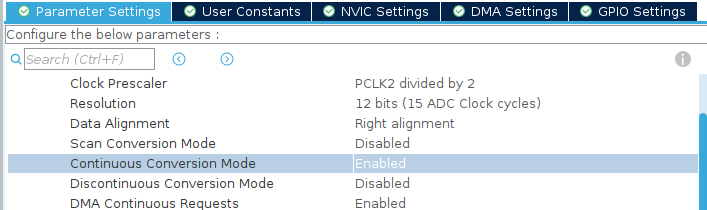
The Continuous Conversion Mode enables the ADC to operate continuously, performing conversions one after another automatically without CPU involvement, while DMA Continuous Requests allows each conversion result to be immediately transferred to memory via DMA. Together, these settings provide a constant data stream: the ADC continuously measures the signal, and DMA automatically writes the values into a buffer, completely freeing the CPU.
Next, let’s create a buffer to store the measured values.
uint16_t adc_buffer[10];//Buffer for DMA
HAL_ADC_Start_DMA(&hadc1,(uint32_t*)adc_buffer,10);//Start ADC with DMA
To make the system manageable, let’s add a timer that triggers, for example, once per second to start processing the accumulated data. Unlike constant polling in the main loop, a timer allows us to set a precise update period: the ADC with DMA continuously collects values, and on the timer interrupt, we simply take the ready buffer, process it, average it, and send the result via UART.
Let’s configure the following settings for Timer 2 (TIM2).
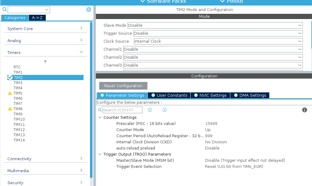
In this setup, the timer will trigger once per second, given the 16 MHz input clock.
void HAL_TIM_PeriodElapsedCallback(TIM_HandleTypeDef *htim)
{
    if(htim->Instance==TIM2)
    {
        uint32_t sum=0;
        for(int i=0;i<10;i++)
        {
            sum+=adc_buffer[i];
        }
        uint32_t adc_avg=sum/10;
        float voltage=(adc_avg/4095.0f)*3.3f;
        char buffer[50];
        int volts=(int)voltage;
        int cents=(int)((voltage-volts)*100);
        int len=sprintf(buffer,"Voltage: %d.%02d V\r\n",volts,cents);
        HAL_UART_Transmit(&huart3,(uint8_t*)buffer,len,HAL_MAX_DELAY);
    }
}
When the timer triggers, it first checks that the source is the correct timer—in our case, TIM2. Then it sums the values in the adc_buffer, calculates the average, converts it to voltage, splits the result into integer and fractional parts, and formats it into a string. Finally, the calculated voltage is sent via UART, providing periodic output of the measured data without involving the main program loop.
As a result, in the terminal we see something like this:
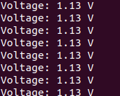
Using an ADC together with DMA and a timer allows continuous and automatic reading of analog signals without blocking the main program loop. DMA handles transferring data from the ADC to a buffer, while the timer periodically triggers processing of these values and sending them via UART. This approach improves measurement accuracy, reduces CPU load, and makes the system more responsive and convenient for integration into real-world projects.