

USART — Universal Synchronous/Asynchronous Receiver/Transmitter is a universal synchronous/asynchronous transceiver. From the name itself, it’s clear that this is an interface for transmitting and receiving data between digital devices.
An important aspect is asynchronous operation — meaning there is no clock signal from the other device to indicate when to sample the bits. Therefore, both devices must be synchronized in terms of speed, which is called the baud rate.
In simplified terms, the idea is as follows: the receiver gets a byte of data along with the start and stop bits, and within a defined time frame it samples the signal. Thanks to the agreed baud rate, the receiver knows exactly which moment in time corresponds to each bit.
Next, we’ll go through the main registers, operating modes, and implement some practical examples with real devices.
Main USART Registers.
There are a total of seven USART registers. Let’s take a closer look at each of them.
1) USART_SR (Status Register) – Status register.
Contains transmission and reception status flags.
Flags:
- TXE – Transmit Data Register Empty. Indicates the transmit buffer is empty.
- TC (bit 6) – Transmission Complete. Indicates that the transmission is fully finished.
- RXNE – Read Data Register Not Empty. Indicates that a new byte has been received.
- There are also error flags: NE, FE, PE, ORE.
2) USART_DR (Data Register) – Data register.
This is the main register when working with USART.
- Write data here to transmit.
Read from here to get received data.
Although it is a single register, transmission and reception can occur simultaneously thanks to the internal separation into different shift registers.
3) USART_BRR (Baud Rate Register) – Baud rate register.
This register sets the transmission speed, measured in baud.
It is important that both the receiver and transmitter are configured with the same baud rate. Only a small deviation of a few percent is acceptable; otherwise, reliable communication cannot be guaranteed.
4) USART_CR1 (Control Register 1) – Control register 1.
Key bits:
- UE – USART Enable.
- M – Word length: 0 = 8 bits, 1 = 9 bits.
- PCE – Parity Control Enable.
- PS – Parity Selection: 0 = even, 1 = odd.
- TXEIE – TXE interrupt enable.
- RXNEIE – RXNE interrupt enable.
- TE – Transmitter Enable.
RE – Receiver Enable.
5) USART_CR2 (Control Register 2) – Control register 2.
Key bits:
- STOP – Number of stop bits.
- CLKEN – Clock enable (for synchronous mode).
CPOL, CPHA – Clock polarity and phase.
6) USART_CR3 (Control Register 3) – Control register 3.
Contains configuration bits for DMA settings.
7) USART_GTPR (Guard Time and Prescaler Register) – Contains the prescaler and guard time configuration bits.
USART Frame Format.
In the idle state, the UART transmitter output remains at a high level.
Transmission of a byte begins with a start bit, which is always 0 (low level). From the moment the start bit is detected, the receiver begins its internal timing.
Next come the data bits (0–7).
Optionally, a parity bit (one or two) may be included. During transmission, this bit is set to 0 or 1 depending on the number of ones in the previous data bits:
- If the number of ones is even → parity bit = 0.
- If the number of ones is odd → parity bit = 1.
The data transmission ends with a stop bit, which is always 1 (high level).
Thus, a UART frame looks like this:
Start bit → Data bits → Parity bit → Stop bit
For the UART interface, standard baud rates are commonly used. The most frequently used values include 4800, 9600, 19200, 38400, 57600, and 115200 baud. The higher the baud rate, the greater the transmission speed, but also the higher the probability of errors.
Connection Diagram.
The wiring is quite simple — only two lines are required.
- Tx (transmit) – the line used by the device to send data.
- Rx (receive) – the line used by the device to receive data.
The connection is straightforward:
- Tx of the first device → Rx of the second device
- Rx of the first device → Tx of the second device
USART is a point-to-point interface, meaning it is primarily designed for communication between two devices.
If you need multiple slave devices, it is better to choose SPI or I²C.
Practical Implementation.
I am using the STM32F4 Discovery board, which has six USART peripherals.
Let’s connect USART2 to USART3, transmit some data, and display the results on the screen.
For proper operation, it is important that both USARTs are configured with the same parameters.
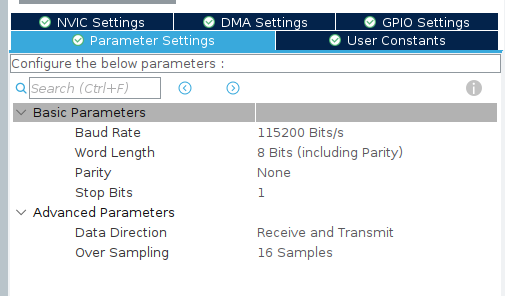
USART Configuration
- Baud Rate – 115200 bit/s (data transfer speed)
- Word Length – 8 bits (length of the data frame)
- Parity – none (no parity bit)
- Stop Bits – 1 stop bit
Don’t forget to enable interrupts.
We then generate our code using CubeIDE. As a result, we can see that the USART initialization functions are already prepared.
MX_GPIO_Init();
MX_USART2_UART_Init();
MX_USART3_UART_Init();
To transmit data, we use the function:
HAL_UART_Transmit_IT(&huart2, txData, sizeof(txData) - 1);
- &huart2 – pointer to the UART structure containing all configuration parameters.
- txData – array holding the string to transmit.
- sizeof(txData)-1 – buffer size minus one, so that the null terminator (\0) is not sent.
Similarly, for receiving data, we use the function:
HAL_UART_Receive_IT(&huart3, rxData, sizeof(txData) - 1);
Let’s add the initial variables.
uint8_t txData[] = "Hello from USART"; // data to transmit
uint8_t rxData[sizeof(txData)]; // buffer for reception
In the USER CODE BEGIN 4 section, we add callbacks to visually verify that transmission and reception have occurred.
void HAL_UART_TxCpltCallback(UART_HandleTypeDef *huart)
{
    if (huart->Instance == USART2) // check that this is USART2
    {
        // For example, turn on an LED when transmission is complete
        HAL_GPIO_WritePin(GPIOD, GPIO_PIN_12, GPIO_PIN_SET);
    }
}

void HAL_UART_RxCpltCallback(UART_HandleTypeDef *huart)
{
    if (huart->Instance == USART3)
    {
        HAL_GPIO_WritePin(GPIOD, GPIO_PIN_13, GPIO_PIN_SET);
        HAL_UART_Receive_IT(&huart3, rxData, sizeof(txData) - 1);
    }
}
They are triggered by the transmit and receive interrupts, respectively.
After the transmission is complete, we turn on the LED on PIND12, and after reception, on PIND13, then restart the receive function.
For visual verification, you can either print messages to the terminal or connect a display.
How to connect a display in this article https://beartronix.com/st7735-stm32
How to connect a terminal via UART can be read here https://beartronix.com/pl2303hx-usb-to-uart-converter
All that remains is to call our functions and check their operation.
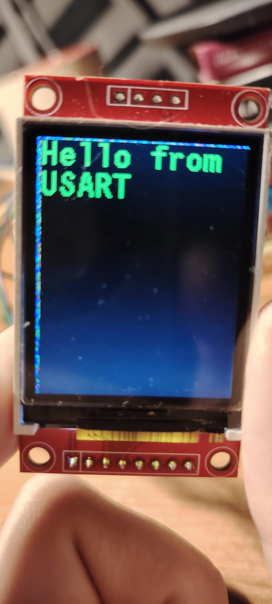
HAL_UART_Receive_IT(&huart3, rxData, sizeof(txData) - 1);
HAL_UART_Transmit_IT(&huart2, txData, sizeof(txData) - 1);
ST7735_FillScreen(ST7735_BLACK); // clear the screen
HAL_Delay(2000);
ST7735_DrawString(0, 0, (char*)rxData, Font_11x18, ST7735_GREEN, ST7735_BLACK);
We can see that the LEDs are lit and the text appears on the display, indicating that the data was successfully transmitted via UART.
In conclusion, we explored the structure and operating principles of the USART interface, reviewed its main registers and frame formats, and implemented a practical example of data transmission and reception between two modules on the STM32F4 Discovery. By using HAL functions with interrupt support, we were able to set up bidirectional communication, verify its operation with LEDs, and display the result on a screen. This approach not only helps to understand the basics of UART/USART operation but also provides practical experience that will be useful when developing real-world microcontroller projects.