

PL2303HX is a popular USB-to-UART converter that allows connecting microcontrollers to a computer through a standard USB port. The module is based on the Prolific PL2303HX chip, which provides the conversion of USB signals into a UART serial interface. Such an adapter is often used in the development and debugging of microcontroller projects, as it makes it easy to establish data exchange with a PC. In our article, we will use PL2303HX to connect a microcontroller to a computer via UART and display characters in the terminal. We will be working under Linux.
Connection diagram
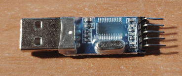
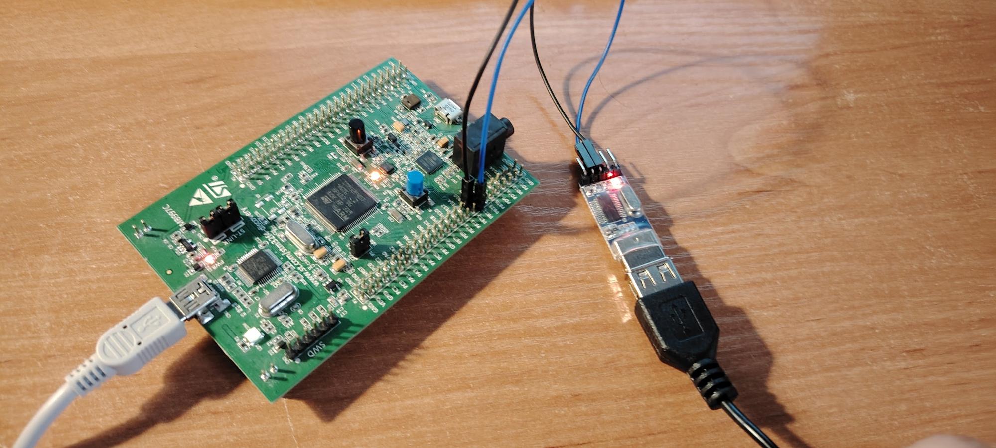
The module itself looks like this
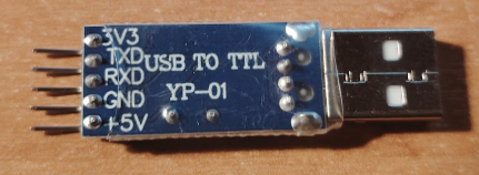
The PL2303HX module has five main pins:
- 3.3V
- TXD – data transmission (module output, connects to the microcontroller’s RX)
- RXD – data reception (module input, connects to the microcontroller’s TX)
- GND – ground
- 5V
Since our module is powered via USB, the connection diagram is very simple. You just need to connect the microcontroller’s TX to the module’s RX and the microcontroller’s RX to the module’s TX. This is enough for data transmission and reception.
Microcontroller UART Configuration
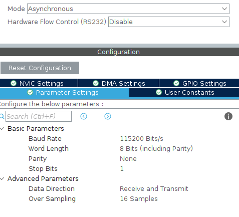
We are working in CubeIDE. The configuration is standard: asynchronous mode, 115200 bit/s baud rate, 8-bit data length, no parity bit, and one stop bit.
After setting the configuration, we generate our code. Let’s add a few lines: a variable that will hold the string we want to transmit.
/* USER CODE BEGIN PV */
char msg[] = "Hello from microcontoller\r\n";
/* USER CODE END PV */
And the transmission function itself.
while (1)
{
HAL_UART_Transmit(huart3, (uint8_t*)msg, sizeof(msg) - 1, HAL_MAX_DELAY);
HAL_Delay(1000);
}
Thus, we will send our string via UART once every second.
Terminal Setup.
We have finished configuring the microcontroller; now let’s set up our terminal to receive data. First, let’s check where our device is located. In the terminal, type the following:
dmesg | grep tty
Usually, it is /dev/ttyUSB0 or /dev/ttyUSB1. In my case, it is /dev/ttyUSB0.
Grant access permissions
sudo usermod -aG dialout $USER
To display the data, we will use minicom (a utility that allows communication with devices via serial ports). First, let’s install it.
sudo apt install minicom
Then, we launch it.
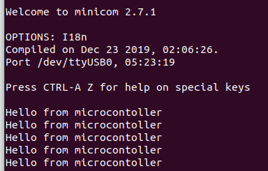
minicom -b 115200 -D /dev/ttyUSB0
As a result, our string will be sent every second.
To exit minicom, press Ctrl + Shift + A, then X.
Data Transmission to the Microcontroller.
We have handled reception. Now let’s send a command to control our microcontroller. For example, I want to type led on in the terminal to turn on the LED on our board, then type led off to turn it off.
Set pin PD13 (we are working with STM32F4 Discovery) as an output. This will be our LED. Next, we will write an interrupt function (don’t forget to enable UART interrupts in your CubeIDE).
void HAL_UART_RxCpltCallback(UART_HandleTypeDef *huart)
{
if (huart->Instance == USART3) { // check that this is our UART
        char c = rxBuf[0];
if (c == '\r' || c == '\n') { // end of string
        cmdBuf[idx] = '\0';
        idx = 0;
if (strcmp(cmdBuf, "led on") == 0) {
        HAL_GPIO_WritePin(GPIOD, GPIO_PIN_13, GPIO_PIN_SET); // turn on LED
        char msg[] = "LED ON SUCCESS\r\n";
        HAL_UART_Transmit(&huart3, (uint8_t*)msg, strlen(msg), HAL_MAX_DELAY);
} else if (strcmp(cmdBuf, "led off") == 0) {
        HAL_GPIO_WritePin(GPIOD, GPIO_PIN_13, GPIO_PIN_RESET); // turn off LED
        char msg[] = "LED OFF SUCCESS\r\n";
        HAL_UART_Transmit(&huart3, (uint8_t*)msg, strlen(msg), HAL_MAX_DELAY);
} else {
        char msg[] = "Unknown command\r\n";
        HAL_UART_Transmit(&huart3, (uint8_t*)msg, strlen(msg), HAL_MAX_DELAY);
}
} else {
if (idx < RX_BUF_SIZE - 1) {
        cmdBuf[idx++] = c; // add character to command buffer
}
}
// re-enable reception
HAL_UART_Receive_IT(&huart3, rxBuf, 1);
}
}
The function checks that the interrupt came from our UART, then appends the received character from the computer to a variable. If the command matches “led on”, it turns on the LED; if it matches “led off”, it turns off the LED. If an unknown command is received, it sends “Unknown command”. Finally, it re-enables reception.
Next, let’s add the variables needed for this functionality.
uint8_t rxBuf[1]; // receive 1 byte at a time
char cmdBuf[RX_BUF_SIZE]; // command buffer
uint8_t idx = 0;
Start sending a string and immediately enable reception.
HAL_UART_Transmit(&huart3, (uint8_t*)msg, sizeof(msg) - 1, HAL_MAX_DELAY);
HAL_UART_Receive_IT(&huart3, rxBuf, 1);
Open our minicom terminal. We can see that the string “Hello from microcontroller” has arrived immediately. To be able to type commands, we need to enable echo mode. Press Ctrl + A, then Z to open the menu, and press E. Echo mode is now enabled, and we can enter our commands. Try typing led on, and the LED lights up while the terminal displays a message confirming the command was executed successfully.
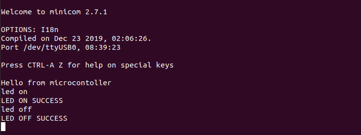
We connected the PL2303HX module to the microcontroller via the UART interface and linked it to a computer through USB. Using a simple STM32 program, we sent string messages and numbers, which were successfully displayed in the terminal. In the other direction, we sent a command through the terminal, and the microcontroller processed it by turning on the LED. This way, we verified two-way data exchange and peripheral control via UART.