

Display Specifications
In this project, we will connect the ST7735 display to the STM32F4 Discovery board featuring the STM32F407VGT6 microcontroller. The display itself looks like this:
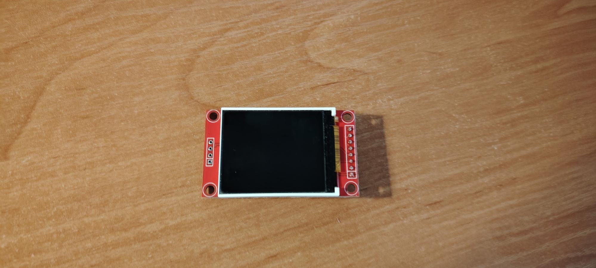
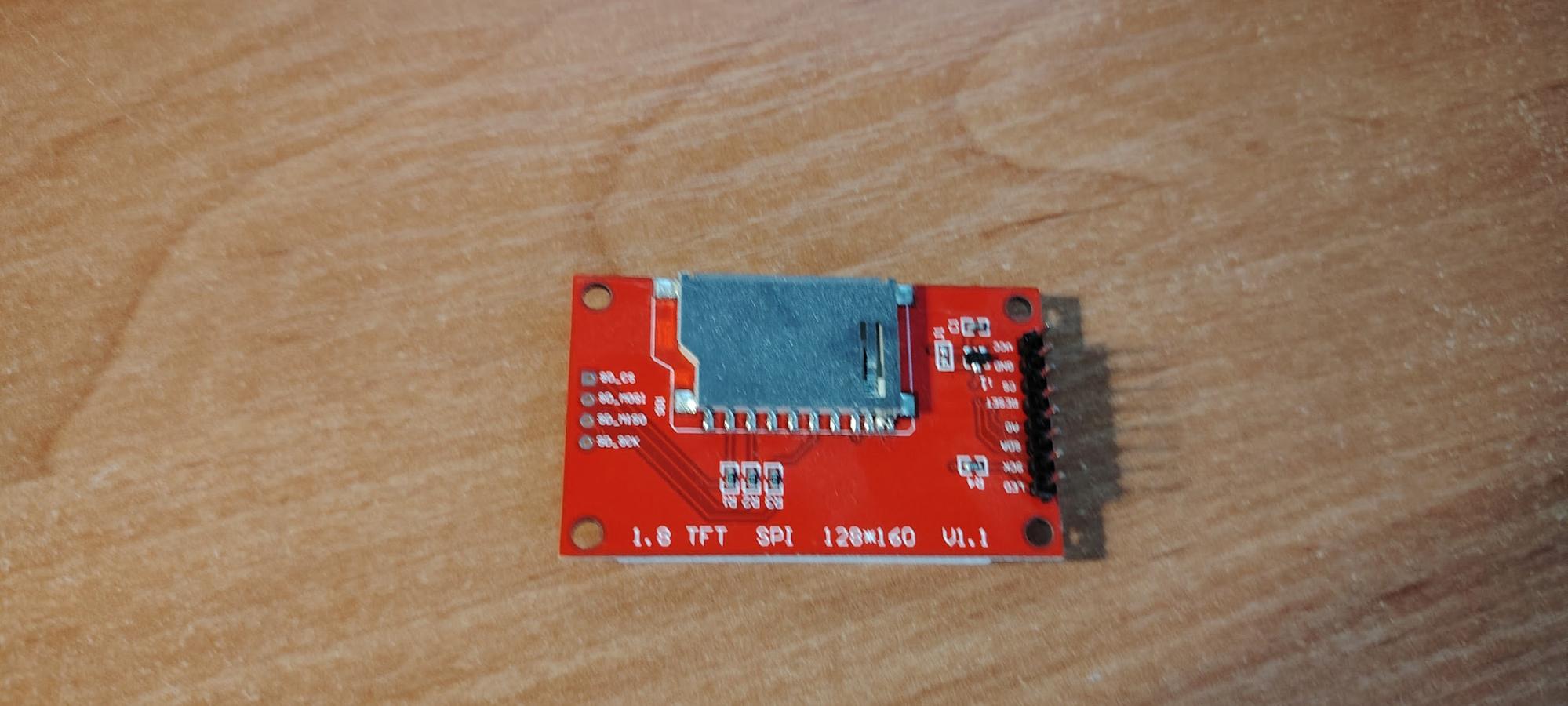
The display is used to output data from your microcontroller. It features a 1.8-inch diagonal with a resolution of 128×160 pixels. The display uses a TFT LCD (Thin-Film Transistor Liquid Crystal Display) matrix. One of its advantages is the SPI interface, which requires only a few pins for connection. It also includes a built-in backlight and has ready-to-use libraries available for development. The display operates at 3.3V, which is standard for microcontrollers.
Configuration in CubeIDE
The display communicates via the SPI protocol. It only receives data and does not send anything back. Let’s start by configuring the project in CubeIDE.
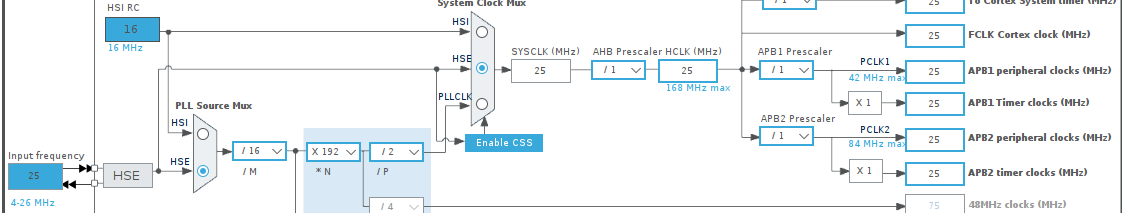
First, open the Clock Configuration tab. We’ll be using SPI1 on the microcontroller, which is located on the APB2 peripheral clock bus.
Adjust the clock settings to achieve a frequency of 25 MHz for SPI1.
Next, go to the Connectivity tab and select SPI1.
In the Mode field, choose Transmit Only Master, since the display does not send any data back.
Then configure the following settings:
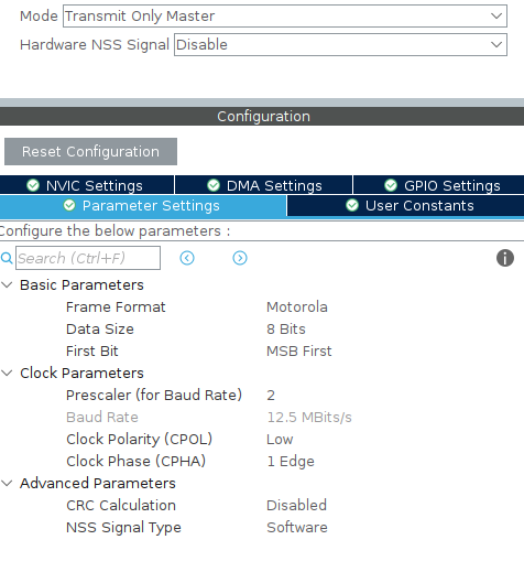
Frame Format — Motorola.
Data Size — the standard setting for the display is 8 bits.
First Bit — ST7735 uses MSB First (the most significant bit is transmitted first).
Speed configuration: the ST7735 supports speeds up to 15 MHz.
We set the Prescaler to 2, which results in a baud rate of 12.5 Mbits/s.
Clock Polarity (CPOL) — ST7735 typically requires CPOL = 0, meaning the SCK line should remain low when idle.
Clock Phase (CPHA) — 1 Edge (data is captured on the first clock transition).
CRC — Disabled (cyclic redundancy check is turned off).
Don’t forget to generate the code. That completes the configuration.
Wiring Diagram
Our microcontroller looks like this.
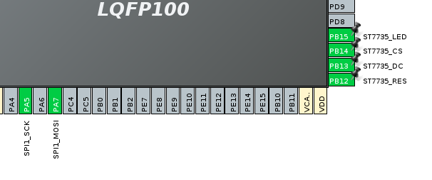
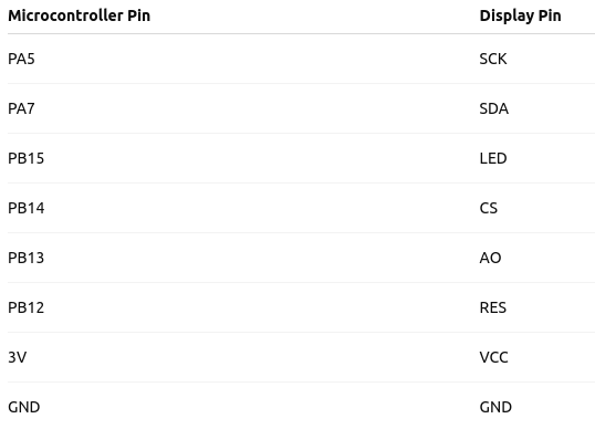
Pin PA5 is connected to the display’s SCK pin and is responsible for the SPI clock signal, while PA7 is connected to the SDA pin, handling data transmission. Pin PB15 controls the display’s backlight and connects to the LED pin. Pin PB14 is used for chip select (CS). Pin PB13 connects to the AO pin, which determines the transmission mode—command or data; for sending data to the display, this pin is set to a high level. Pin PB12 connects to the RES pin and is used for the hardware reset of the display. Additionally, 3.3V power must be supplied to the VCC pin, and the microcontroller’s ground (GND) must be connected to the display’s ground. The display’s CS pin is not needed in this setup because there is only one display connected.
Program Code
We use the following library: https://github.com/afiskon/stm32-st7735
Place the header files fonts.h, st7735_cfg.h, and ST7735.h into the Core/Inc folder, and the source files fonts.c and ST7735.c into the Core/Src folder.
Include the header files:
/* USER CODE BEGIN Includes */
#include "fonts.h" #include "ST7735.h"
/* USER CODE END Includes */
Next, in the main function, initialize the display, turn on the backlight, set the screen orientation, and clear the screen:
/* USER CODE BEGIN 2 */
ST7735_Init();
ST7735_Backlight_On();
ST7735_SetRotation(r);
ST7735_FillScreen(ST7735_BLACK);
/* USER CODE END 2 */
Displaying a number
Define the initial counter variable:
/* USER CODE BEGIN PV */
int counter = 0;
/* USER CODE END PV */
Initialize the function for displaying the number:
void sendNumber(int loc_counter) {
 char buffer[10];
 sprintf(buffer, "%d", loc_counter); //Convert number to string
 ST7735_DrawString(0, 3*10, buffer, Font_11x18, ST7735_GREEN, ST7735_BLACK);
 }
A character array of length 10 is created. This array is used as a buffer to store the string representation of the number loc_counter in text form.
The array is large enough to hold up to 10 characters. The sprintf function converts the integer loc_counter into a string and stores the result in the buffer array.
The next line, ST7735_DrawString, is a function call from the ST7735 display driver library. It outputs the string containing the number onto the screen.
Function arguments:
- 0: x-coordinate — the horizontal position of the text on the screen.
- 3 * 10: y-coordinate — the vertical position of the text on the screen, calculated as 30 pixels (3 lines × 10 pixels per line).
- buffer: pointer to the string to be displayed on the screen.
- Font_11x18: font used to render the text (for example, character size is 11×18 pixels).
- ST7735_GREEN: text color (green).
- ST7735_BLACK: background color behind the text (black).
Let’s call our function inside the while loop:
/* USER CODE BEGIN WHILE */
while (1)
{
 HAL_Delay(1000);
 sendNumber(counter);
 counter++;
}
/* USER CODE END WHILE */
/* USER CODE BEGIN 3 */
Here’s a function to display a string that includes a number:
void sendString(const char* loc_string)
{
ST7735_DrawString(0, 3*10, loc_string, Font_11x18, ST7735_GREEN, ST7735_BLACK);
}
Call it inside the loop like this:
ST7735_FillScreen(ST7735_BLACK);
char buffer[50];
sprintf(buffer, "Hi! I'm string %d", counter);
sendString(buffer);
On the display, you will see the text:
Hi! I’m string 0