

Overflow and Compare Interrupts
In the previous article, we introduced timers (link here). Now let’s take a closer look at one of the most commonly used timer modes — overflow interrupts.Overflow (and compare) interrupts are widely used in real-time systems for generating periodic events, measuring time intervals, creating delays, and more.We’ll start with a brief overview of what interrupts are in general, and then explain the concepts of overflow and compare in the context of timers.
What are interrupts?
Interrupts are a mechanism that responds to an event occurring on the microcontroller.They can be external (such as signals from buttons, sensors, or other devices) or internal, meaning they’re generated by internal peripherals like timers, ADCs, UART, etc. In our case, when working with a timer, we’re dealing with an internal interrupt. For example, when the timer reaches a specified value, an interrupt is triggered. But what exactly happens at that moment?
- Event occurrence. When the timer reaches its maximum value (overflow) or a specific threshold (compare match), a corresponding flag is set in a status register.
- Interrupt request.If interrupts are enabled (the interrupt enable bit is set), the microcontroller temporarily pauses the main program and jumps to the interrupt handler — a special subroutine in your code. It also saves the point in the program where it left off, so it can return to it later.
- Interrupt handler execution.The code inside the interrupt handler is executed.
- Return to the main program. After the handler finishes, the microcontroller returns to the exact spot in the main program where it was interrupted.
Overflow and Compare Events
Overflow interrupt is a type of interrupt that occurs when the timer counter (defined by the ARR register) reaches its maximum value.
Let’s take Timer 4 on the STM32F407VGT6 microcontroller as an example. It’s a 16-bit timer, which means its maximum count value is 65,535 (since counting starts from zero).
In practice, this means that as soon as the value in the ARR register reaches 65,535, an overflow interrupt is triggered.
Compare interrupt, on the other hand, occurs when the timer counter reaches a specific predefined value. The key difference is that we manually set this value in the Compare register (usually CCRx), which allows for precise timing and interval control.
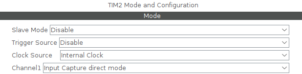
Let’s look at how both of these types of interrupts can be used in real-world applications.The task is as follows: using compare interrupts, make an LED on the board blink with a period of one second. We will use Timer 2 on the STM32F407VGT6 microcontroller.The first configuration is the clock source. Go to the timer settings (Timers-TIM2), locate the Clock Source option, and select Internal Clock. We will use the first channel in Input Capture Direct mode.
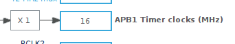
Next, we need to determine which bus the timer is connected to. In our case, Timer 2 is connected to the APB1 Timers Clocks bus. (If you’re not sure, it’s best to double-check this in the datasheet.)
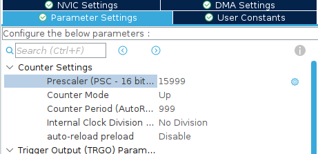
Set the Prescaler value to 15999 and the Counter period to 999.
Let’s move on to the calculations.
The clock frequency is 16 MHz. Our prescaler is 15999 (since counting starts from zero, it is always one less).
The frequency after the prescaler is:
16,000,000 / 16,000 = 1,000 Hz
To calculate the time for each trigger, take the value set in the Counter Period register + 1 and divide it by the frequency obtained:
1,000 / 1,000 (Hz) = 1 second
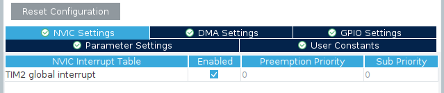
Don’t forget to enable the interrupts for our timer.
Here’s the program code.
After generating the code, we need to add a few lines to start and handle the interrupt. In the code block, add the following lines:
__HAL_TIM_CLEAR_FLAG(&htim2, TIM_SR_UIF);
HAL_TIM_Base_Start_IT(&htim2);
The first line clears the timer overflow flag (UIF — Update Interrupt Flag). This is important to do before starting the timer to ensure that the interrupt doesn’t trigger immediately due to a previously set flag. The flag is automatically set after initialization in CubeIDE.
The second line starts the timer in interrupt generation mode, meaning the corresponding interrupt will be triggered.
When the timer overflows (the timer counter reaches the value in the ARR register, in our case 999), the program enters the interrupt vector corresponding to the specified timer — for example, TIM2_IRQHandler for Timer 2. At this stage, we have two ways to handle the interrupt:
- Directly work with the interrupt handler function — TIM2_IRQHandler.
- Use the HAL callback function — HAL_TIM_PeriodElapsedCallback.
If you are using the HAL library, it is recommended to use HAL_TIM_PeriodElapsedCallback. This is a more flexible and safer approach, as HAL itself calls this callback within the TIM2_IRQHandler, maintaining all internal logic and compatibility.However, if you are not using HAL or need maximum low-level control, you can write code directly in TIM2_IRQHandler.
In our case, we are using HAL, so we will handle the interrupt through HAL_TIM_PeriodElapsedCallback. For example, in this function, we will toggle the state of the green LED on our development board:
HAL_TIM_PeriodElapsedCallback(TIM_HandleTypeDef)
{
  if(htim->Instance == TIM2)
 {
  HAL_GPIO_TogglePin(GPIOD, GPIO_PIN_12);
 }
}
As a result, our LED will blink once every second.