

What is a Timer?
A timer is a hardware module within a microcontroller that enables time measurement, delay generation, and process control. It functions as a counter that increments or decrements at a specific rate determined by the clock signal. Timers are essential for precise time tracking, signal generation (e.g., PWM), frequency measurement, and many other tasks—few programs operate without at least one timer.
In this article, we’ll focus on the STM32F407VGT6 microcontroller, but everything discussed applies to other STM32 family microcontrollers as well.
Types of Timers
Each microcontroller has several built-in timers. In our case, there are 14, categorized into three types: Basic Timers, General-Purpose Timers, and Advanced Timers.
- Basic Timers – The simplest type, used for creating delays and triggering events at set intervals. They do not have output channels and do not support PWM.
- General-Purpose Timers – More versatile, capable of not only counting time but also generating signals, measuring pulse durations, and operating in PWM mode.
- Advanced Timers – The most feature-rich, designed for complex tasks such as motor control, synchronization with other peripherals, and more.
For a detailed list of timers available in your microcontroller, refer to the datasheet. Below is the table for the STM32F407VGT6:
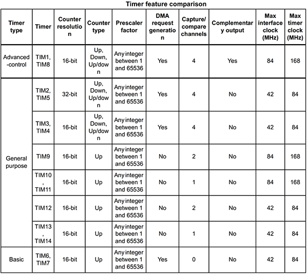
From the table, we can see that there are two advanced timers (TIM1, TIM8), two basic timers (TIM6, TIM7), and the rest are general-purpose timers.
Timer Settings and Calculation
Let’s go through a practical example to calculate our timer so that it triggers at a specific interval. But first, we need to understand what a timer counter is.
The timer counter is the main register that increments or decrements with each timer clock cycle. Depending on the timer’s bit width (shown in the Counter resolution column in the datasheet), the counter can range from 0 to 65,535 (2¹⁶ – 1) for a 16-bit timer or 0 to 4,294,967,295 (2³² – 1) for a 32-bit timer.
For example, if we enable a 16-bit timer running at 16 MHz with no prescaler, it will reach its maximum value in about 4 ms, which is quite fast. To slow it down, we use a prescaler.
The prescaler divides the timer clock frequency by a specified factor. Let’s say our clock is 16 MHz, and we set the prescaler to 8.
Now, let’s calculate the new timer frequency:
Ftimer=16MHz/8MHz=2MHz
Now, let’s determine the overflow time for a 16-bit timer. The maximum value a 16-bit counter can reach is 65,536 (0 to 65,535), but you can set a custom value within this range depending on your requirements (explained further below).
Tfull=65536/2MHZ=32.768ms
Our timer will overflow in 32.768 ms, triggering a timer interrupt event.
Now, let’s explore timer configuration in CubeIDE and some key aspects to consider.
Open the Timers Tab
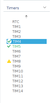
In the .ioc file, navigate to the Timers section and select the desired timer. Let’s take Timer 4 (TIM4) as an example.
Inside the Parameter Settings tab, you’ll find various timer configuration options, including prescaler, counter mode, and auto-reload register (ARR).
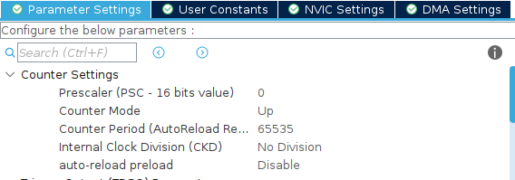
Prescaler
This is the clock prescaler. The default value is set to 0, but in reality, it functions as 1 because the division factor is PSC + 1. For example, if you need a prescaler of 8, you must set it to 7. Always subtract 1 from the desired value when configuring the register.
Counter Mode
This setting defines how the counter (CNT) increments or decrements between 0 and ARR. There are three modes:
- Up – The standard mode. The timer counts from 0 to ARR, then resets to 0 and continues.
- Down – The timer starts at ARR and counts down to 0.
- Center-Aligned – The timer first counts up to ARR, then down to 0. Depending on Mode 1, 2, or 3, event generation occurs at different points.
The Up mode is the most commonly used, as it suits most tasks, including time measurement and PWM signal generation.
Counter Period (Auto-Reload Register, ARR)
This register defines the value at which the timer resets and starts counting again (in Up mode). Like the Prescaler, you need to subtract 1 from the desired value. The default is 65535 for a 16-bit timer, but you can adjust it based on your calculations within the counter’s range.
These three settings are fundamental for working with timers. We will cover additional settings later.
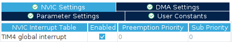
Enabling Timer Interrupts
One crucial step is enabling timer interrupts. This is done in the NVIC Settings tab.
Timer Channels
Most STM32 timers have 1 to 4 channels, allowing multiple functions to run simultaneously. Each channel operates independently and can be used in different modes, such as:
PWM (Pulse Width Modulation),Input Capture (measuring external signal timing),Output Compare (generating specific waveforms),Other advanced features
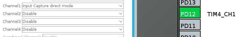
Each channel is mapped to specific GPIO pins. When you select a channel (e.g., TIM4 Channel 1) in Input Capture Direct Mode, CubeIDE will automatically highlight the corresponding pin (PD12 in this case). This mapping is predefined and depends on the specific STM32 model.
Timer Channel Modes
STM32 timers support several key operating modes that enable a wide range of applications. The main ones include:
- Input Capture (IC) – Measures incoming signal timing
- Output Compare (OC) – Triggers events based on counter values
- PWM Mode – Generates pulse-width modulation signals
These modes form the foundation for more advanced timer applications in microcontrollers.
Input Capture Mode (IC)
Used to measure the time of a signal’s arrival or its duration. The timer captures the moment of a level change (rising or falling edge) and stores the counter value in the CCR register. This mode is commonly used with encoders, ultrasonic sensors, and communication protocols.
Output Compare Mode (OC)
Triggers an event or changes the state of an output pin when the timer reaches a predefined value. When the counter matches the compare register (CCR), an event occurs, allowing for precise timing control.
PWM Mode
Used to generate a pulse-width modulated (PWM) signal, where the duty cycle (active time within a fixed period) can be adjusted. This is essential for motor control, LED dimming, and power regulation.
That covers the basics! We’ve explored what timers are, how they work, and their key configurations like prescalers, counting modes, and operational modes. With this knowledge, you can confidently integrate timers into your STM32 projects.