

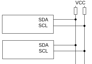
Connection diagram.
Two-wire interface:
SCL (Serial Clock) – clock line.
SDA (Serial Data) – data line.
Each device connects its pins to the pins with the same name of other devices. Up to 127 devices can be on one bus. Pull-up resistors are mandatory for the device to work.
The maximum bus length is limited, usually 1–2 meters, otherwise the signals become distorted.
I2C can operate at different speeds:
- Standard (100 kHz)
- Fast (400 kHz)
- Fast Plus (1 MHz)
- High Speed (3.4 MHz)
Data transmission and frame format.
Data exchange is initiated by the master device. It generates clock signals on the SCL line, which have a certain periodicity, but can be delayed by the receiver if it is not yet ready to accept the next byte of data.
In the idle state, both SDA and SCL lines are in a high state.
The data exchange procedure begins with the master device generating the START condition.
- Start condition.
SCL = 1.
SDA goes to 0.
- Addressing
To determine which slave the master is addressing, an address byte must be transmitted. It consists of the first seven bits (the slave address) + the read/write bit. After the address byte is sent on the bus, each device in the system compares the first seven bits after the START signal with its own address. If the addresses match, the device considers itself selected as a slave-receiver or as a slave-transmitter, depending on the state of the direction bit. Then the slave pulls SDA low (0), confirming the reception of the byte. - Data transmission.Next comes the data byte from the master. The acknowledgment bit (0 for successful transmission and 1 for an error) is on the left. The acknowledgment bit from the receiver is generated after each data byte. Data bytes are sent as many times as needed.
- End of transmissionSDA goes to 1
SCL = 1
Data transmission diagram
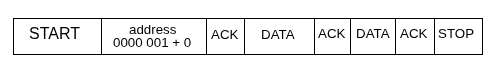
Master START – address – slave ACK – master DATA – slave ACK – master DATA – slave ACK – master STOP
ACK (Acknowledgment) — a signal that the data byte is received (0 on SDA). Instead of ACK, there can be NACK (Not Acknowledged) — a signal that the data byte is not received (1 on SDA).
Arbitration.
I2C supports simultaneous operation of multiple master devices. This can lead to situations where two or more masters try to operate at the same time. Let’s consider a few cases.
In the first case, one master tries to transmit data but detects that the line is busy with another device. In this case, the second master waits for the first transmission to finish before starting its own.
The second case is when two masters try to start transmission simultaneously. I2C uses the open-drain/open-collector principle: if one master releases the line to “1” while another pulls it to “0”, the line always stays at “0”. This ensures that, during simultaneous transmission, the master whose data matches the line state wins arbitration, while the master that tried to send “1” but sees “0” realizes it lost, stops transmission, and waits for the bus to be free.
Main I2C register groups (using STM32 as an example)
Control Registers (CR1, CR2)
- CR1 – enables the peripheral, manages ACK, generates START/STOP.
- CR2 – sets the clock frequency, configures interrupts.
Clock Configuration Register (CCR)
- Determines whether the speed is Standard (100 kHz) or Fast (400 kHz).
- Contains the clock divider value.
TRISE
- Configures the maximum signal rise time to comply with the I2C standard.
SR1 and SR2 (Status Registers)
- SR1 – shows events: START generated, address transmitted, byte received, error (NACK, overrun, etc.).
- SR2 – current status: busy/free, master/slave, address match.
DR (Data Register)
- Used to write a byte for transmission or read a received byte.
OAR1, OAR2 (Own Address Registers)
- Contain the device’s own address when operating as a slave.
I2C Example
For an I2C usage example, let’s take the BMP280 temperature and pressure sensor.
We will read the temperature and output it to the Linux console.
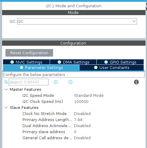
First, configure I2C1 in CubeIDE with the following settings.
The connection diagram is as follows.
BMP280 – STM32
SDA – PB7
SCL – PB6
VCC – 3.3V
GND – GND
CSB – VCC
SDO – GND
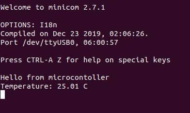
Connect the UART/USB adapter and start minicom in the console. Detailed instructions on how to do this can be found in this article.
https://beartronix.com/pl2303hx-usb-to-uart-converter
Pull-up resistors are required on the SCL and SDA lines. In our case, they are already installed on the module.
Program code.
Let’s set the key parameters.
#define RX_BUF_SIZE 32
#define BMP280_ADDR (0x76 << 1)
#define BMP280_REG_ID 0xD0
#define BMP280_REG_RESET 0xE0
#define BMP280_REG_CTRL_MEAS 0xF4
#define BMP280_REG_CONFIG 0xF5
#define BMP280_REG_TEMP_MSB 0xFA
BMP280_ADDR — the sensor address on the I2C bus. If the SDO pin is connected to GND, the address is 0x76; if connected to VCC, the address changes to 0x77. A 1-bit shift is needed for HAL, which expects an 8-bit address.
BMP280_REG_ID — sensor identification register, allows verifying that the device responds correctly.
BMP280_REG_RESET — software reset register, used to initialize the sensor.
BMP280_REG_CTRL_MEAS — control register for temperature and pressure measurements; used to set operating mode and precision.
BMP280_REG_CONFIG — configuration register, sets filters and standby intervals.
BMP280_REG_TEMP_MSB — address of the most significant byte of the raw temperature data register, which is read for subsequent compensation.
Next, it is necessary to write functions for sensor initialization and temperature conversion. Let’s define the required function prototypes.
/* USER CODE BEGIN PFP */
void bmp280_init(void);
int32_t bmp280_read_temp_raw(void);
uint8_t bmp280_read_reg(uint8_t reg);
void bmp280_write_reg(uint8_t reg, uint8_t value);
void bmp280_read_calib(void);
float bmp280_compensate_temp(int32_t adc_T);
/* USER CODE END PFP */
Let’s write the functions.
/* USER CODE BEGIN 4 */
uint8_t bmp280_read_reg(uint8_t reg)
{
    uint8_t value;
    HAL_I2C_Mem_Read(&hi2c1, BMP280_ADDR, reg, 1, &value, 1, HAL_MAX_DELAY);
    return value;
}

void bmp280_write_reg(uint8_t reg, uint8_t value)
{
    HAL_I2C_Mem_Write(&hi2c1, BMP280_ADDR, reg, 1, &value, 1, HAL_MAX_DELAY);
}

void bmp280_init(void)
{
    uint8_t id = bmp280_read_reg(BMP280_REG_ID);
    // Reset
    bmp280_write_reg(BMP280_REG_RESET, 0xB6);
    HAL_Delay(100);
    // Configuration: temperature + pressure, normal mode
    bmp280_write_reg(BMP280_REG_CTRL_MEAS, 0x27); // Normal mode
    bmp280_write_reg(BMP280_REG_CONFIG, 0xA0); // Filter off
}

int32_t bmp280_read_temp_raw(void)
{
    uint_8_t data[3];
    HAL_I2C_Mem_Read(&hi2c1, BMP280_ADDR, BMP280_REG_TEMP_MSB, 1, data, 3, HAL_MAX_DELAY);
    int32_t raw = ((int32_t)data[0] << 12) | ((int32_t)data[1] << 4) | (data[2] << 4);
    return raw;
}

void bmp280_read_calib(void)
{
uint_8_t data[6];
HAL_I2C_Mem_Read(&hi2c1, BMP280_ADDR, 0x88, 1, data, 6, HAL_MAX_DELAY);
dig_T1 = (uint16_t)(data[0] | (data[1] << 8));
dig_T2 = (int16_t)(data[2] | (data[3] << 8));
dig_T3 = (int16_t)(data[4] | (data[5] << 8));
}

float bmp280_compensate_temp(int32_t adc_T)
{
int32_t var1, var2;
var1 = ((((adc_T >> 3) - ((int32_t)dig_T1 << 1))) * ((int32_t)dig_T2)) >> 11;
var2 = (((((adc_T >> 4) - ((int32_t)dig_T1)) * ((adc_T >> 4) - ((int32_t)dig_T1))) >> 12) * ((int32_t)dig_T3)) >> 14;
t_fine = var1 + var2;
float T = (t_fine * 5 + 128) >> 8;
return T / 100.0f;
}
/* USER CODE END 4 */
This section implements the main functions for working with the BMP280 sensor. The functions bmp280_read_reg and bmp280_write_reg provide low-level reading and writing of the sensor’s registers via I2C. bmp280_init performs sensor initialization, including reset and measurement mode configuration. bmp280_read_temp_raw reads the raw temperature data, and bmp280_read_calib loads the calibration coefficients for accurate calculation. Finally, bmp280_compensate_temp adjusts the raw data using the calibration and returns the temperature in degrees Celsius.
In the main function, we will call our initialization and calibration functions.
bmp280_init();
bmp280_read_calib();
Read the temperature
int32_t raw_temp = bmp280_read_temp_raw();
Convert using the compensation tables
float temp_C = bmp280_compensate_temp(raw_temp);
For convenient output, we will split the obtained value into integer and fractional parts.
int32_t temp100 = (int32_t)(temp_C * 100); // temperature *100
int32_t t_int = temp100 / 100; // integer part
</span>int32_t t_frac = temp100 % 100; // fractional part
And output to the console
char buf[32];
int len = snprintf(buf, sizeof(buf), "Temperature: %ld.%02ld C\r\n", t_int, t_frac);
HAL_UART_Transmit(&huart3, (uint8_t*)buf, len, HAL_MAX_DELAY);
The article demonstrates how to work with the BMP280 sensor on STM32 via I2C: from initialization and register reading to calibration and temperature calculation. We explored how the I2C bus works, reviewed the connection diagram, and the format of transmitted frames. This approach allows obtaining accurate temperature data and serves as a foundation for expanding functionality, such as measuring pressure or recording data in real time.