

SPI interface.
SPI is a serial synchronous full-duplex data transfer interface.
Let’s break down each term separately:
Serial: data is transmitted over a single line, bit by bit.
Synchronous: data transfer is synchronized with a clock signal, which enables faster and more reliable communication.
Full-duplex: the device can transmit and receive data simultaneously.
Master-slave topology: one master controls one or more slave devices.
The devices are connected as follows.
MOSI – Master Output / Slave Input. The master’s output / the slave’s input. Used to transfer data from the master device to the slave.
MISO – Master Input / Slave Output. The master’s input / the slave’s output. Used to transfer data from the slave device to the master.
SCK – Serial Clock. A signal used to generate the clock frequency for data synchronization.
SS – Slave Select. Used to select a slave device by pulling the line low. If there are multiple devices, only one can be active at a time.
SS1, SS2, etc. – used if there is more than one slave device.
It is worth noting that if we are only reading data from the slave device, we only need the SCK and MISO lines, and if we are only writing to the slave, we only need SCK and MOSI.
Data transfer can be done in packets of either 8 bits or 16 bits.
The protocol can be implemented in both hardware and software. We will focus on the hardware implementation, as it is simpler and results in fewer errors. In hardware SPI, we write data into a special register, and the microcontroller automatically sets the required signal levels for data transmission.
Another important point is that the slave cannot initiate communication with the master. To receive data from the slave, the master must send a request to it.
Operating Modes.
SPI supports four operating modes, which are defined by a combination of two parameters:
CPOL (Clock Polarity) – the clock polarity. Determines the idle level of the SCLK line by default, either 0 or 1.
CPHA (Clock Phase) – the sampling phase. Determines on which clock edge (first or second) the data is sampled, regardless of whether it is rising or falling.
Main Functions.
SPI interface can be implemented in the classic way, using registers or HAL functions, or with DMA.
When we implement SPI using the first method, without DMA, two operating modes are possible.
Blocking Mode (Polling) — The processor continuously checks the flags in the SPI (or waits inside the HAL function) until the transfer/reception operation is complete. During this time, the processor is busy and cannot perform other tasks.
Interrupt Mode — The processor starts the transfer and continues executing other tasks. When the transfer is complete, the SPI hardware module generates an interrupt, and a special handler function (callback) in your code is called.
When implemented with DMA, the processor only starts the DMA function and then continues working on other tasks. Meanwhile, the DMA operates in parallel. When the transfer is complete, a callback function is called. This method is convenient for large amounts of data.
DMA can generate several types of interrupts.
Transfer Complete (TC) — transfer is complete. Calls HAL_SPI_RxCpltCallback().
Half Transfer Complete (HT) — half of the buffer has been transferred. Calls HAL_SPI_TxHalfCpltCallback() or, if half of the buffer is received, HAL_SPI_RxHalfCpltCallback().
Transfer Error (TE) — transfer error. Calls HAL_SPI_ErrorCallback().
Abort Complete (ABT) — transfer stopped forcibly. Can be useful if the transfer needs to be stopped urgently.
Main Functions (HAL, without DMA)
Data transmission (blocking)
HAL_SPI_Transmit(&hspi1, uint8_t *pData, uint16_t Size, uint32_t Timeout);
Data reception (blocking)
HAL_SPI_Receive(&hspi1, uint8_t *pData, uint16_t Size, uint32_t Timeout);
Simultaneous transmit and receive (full duplex)
HAL_SPI_TransmitReceive(&hspi1, uint8_t *pTxData, uint8_t *pRxData, uint16_t Size, uint32_t Timeout);
The same functions in interrupt mode (IRQ)
HAL_SPI_Transmit_IT(…)
HAL_SPI_Receive_IT(…)
HAL_SPI_TransmitReceive_IT(…)
Main Functions (HAL, with DMA)
Data transmission via DMA
HAL_SPI_Transmit_DMA(&hspi1, uint8_t *pData, uint16_t Size);
Data reception via DMA
HAL_SPI_Receive_DMA(&hspi1, uint8_t *pData, uint16_t Size);
Full duplex via DMA
HAL_SPI_TransmitReceive_DMA(&hspi1, uint8_t *pTxData, uint8_t *pRxData, uint16_t Size);
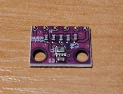
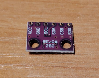
BMP280 Atmospheric Pressure and Temperature Sensor Module.
We will connect the BMP280 pressure and temperature sensor module to the STM32F4 Discovery with the STM32F407VGT6. We will read data from it via SPI and display it on an ST7735 TFT Display, which is also connected via SPI. How to connect the display is described in this article (link), so we won’t repeat it here.
This is what the sensor looks like. Since the project is quite simple, we will use standard blocking functions for data transmission and reception.
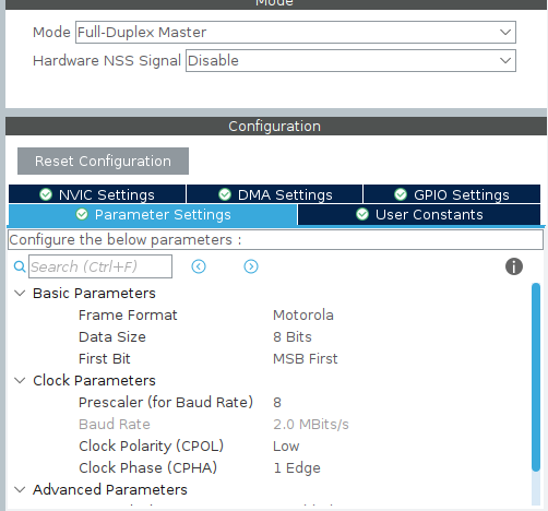
Configuration in CubeIDE
We will use SPI2 of our microcontroller, since SPI1 is occupied by our display. The settings are configured as follows.
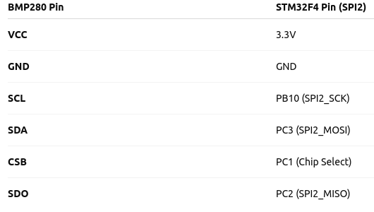
The necessary pins for the connection are highlighted.
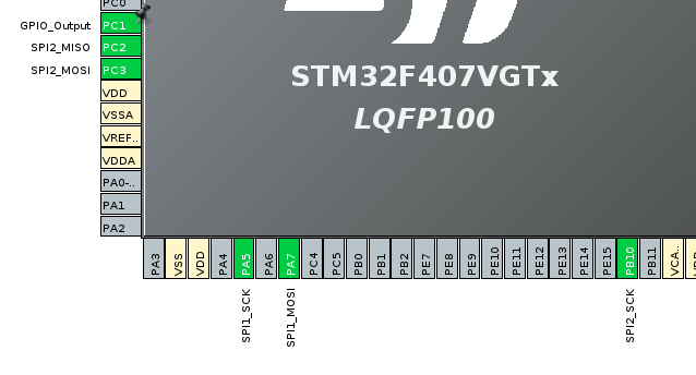
As you can see, PC2 – MISO, PC3 – MOSI, PB10 – SCK. We also need one pin for Chip Select. Let’s use PC1 and set it as an output.
The resulting connection diagram is as follows.
Program Code.
For code clarity, we will create a separate file to work with our sensor. Let’s call it BMP280.c and place it in the Src folder. The corresponding header file BMP280.h goes into the Inc folder.
We will include them in our main.c file.
 /* USER CODE BEGIN Includes */
 #include "BMP280.h"
 /* USER CODE END Includes */
First, we need to check that our sensor is connected and responding correctly. For this, there is a special Chip ID register. In the BMP280, this register is located at address 0xD0. The value in this register is always 0x58 (for the BMP280). If a different value is received, there is an error that needs to be investigated.
We will create a function to read a register.
static uint8_t BMP280_ReadReg(uint8_t reg) {
uint8_t tx = reg | 0x80;
uint8_t rx = 0;
BMP_CS_L();
HAL_SPI_Transmit(&hspi2, &tx, 1, HAL_MAX_DELAY);
HAL_SPI_Receive(&hspi2, &rx, 1, HAL_MAX_DELAY);
BMP_CS_H();
return rx;
}
Setting our CS to high and low levels.
static inline void BMP_CS_L(void) {
HAL_GPIO_WritePin(GPIOC, GPIO_PIN_1, GPIO_PIN_RESET);
}

static inline void BMP_CS_H(void) {
HAL_GPIO_WritePin(GPIOC, GPIO_PIN_1, GPIO_PIN_SET);
}
Don’t forget to change it to your pin if you chose a different one.
We call this function.
uint8_t chip_id = BMP_ReadReg(0xD0);
Next, we will create a function to write to a register.
static void BMP280_WriteReg(uint8_t reg, uint8_t val) {
uint8_t tx[2] = { reg & 0x7F, val };
BMP_CS_L();
HAL_SPI_Transmit(&hspi2, tx, 2, HAL_MAX_DELAY);
BMP_CS_H();
}
The BMP280 chip has calibration coefficients programmed by the manufacturer during sensor testing. When we read raw temperature and pressure data, they don’t mean anything by themselves. To convert them into degrees and Pascals, they need to be applied in formulas that use the calibration coefficients.
For this, we will create a function to get the calibration parameters.
static void BMP280_ReadCalibrationData(void) {
dig_T1 = BMP280_ReadReg(0x88) | (BMP280_ReadReg(0x89) << 8);
dig_T2 = BMP280_ReadReg(0x8A) | (BMP280_ReadReg(0x8B) << 8);
dig_T3 = BMP280_ReadReg(0x8C) | (BMP280_ReadReg(0x8D) << 8);
dig_P1 = BMP280_ReadReg(0x8E) | (BMP280_ReadReg(0x8F) << 8);
dig_P2 = BMP280_ReadReg(0x90) | (BMP280_ReadReg(0x91) << 8);
dig_P3 = BMP280_ReadReg(0x92) | (BMP280_ReadReg(0x93) << 8);
dig_P4 = BMP280_ReadReg(0x94) | (BMP280_ReadReg(0x95) << 8);
dig_P5 = BMP280_ReadReg(0x96) | (BMP280_ReadReg(0x97) << 8);
dig_P6 = BMP280_ReadReg(0x98) | (BMP280_ReadReg(0x99) << 8);
dig_P7 = BMP280_ReadReg(0x9A) | (BMP280_ReadReg(0x9B) << 8);
dig_P8 = BMP280_ReadReg(0x9C) | (BMP280_ReadReg(0x9D) << 8);
dig_P9 = BMP280_ReadReg(0x9E) | (BMP280_ReadReg(0x9F) << 8);
}
Let’s configure the sensor itself. To do this, write 0x27 to the sensor register 0xF4 to enable normal temperature and pressure measurements in continuous mode, and write 0xA0 to register 0xF5 to set the measurement interval to approximately 1 second, disable the digital filter, and use standard SPI. These settings provide simple and stable sensor operation.
We will combine this with the calibration parameters in an initialization function.
void BMP280_Init(void) {
BMP280_WriteReg(0xF4, 0x27);
BMP280_WriteReg(0xF5, 0xA0);
BMP280_ReadCalibrationData();
}
And we call it in main.c.
BMP280_Init();
We will write a compensation function. It is needed to correctly calculate temperature and pressure values. The formulas are taken from the datasheet.
static int32_t BMP280_CompensateTemp(int32_t adc_T) {
int32_t var1 = ((((adc_T >> 3) - ((int32_t)dig_T1 << 1))) * ((int32_t)dig_T2)) >> 11;
int32_t var2 = (((((adc_T >> 4) - ((int32_t)dig_T1)) * ((adc_T >> 4) - ((int32_t)dig_T1))) >> 12) * ((int32_t)dig_T3)) >> 14;
t_fine = var1 + var2;
return (t_fine * 5 + 128) >> 8; // °C * 100
}

static float BMP280_CompensatePressure(int32_t adc_P) {
int64_t var1, var2, p;
var1 = ((int64_t)t_fine) - 128000;
var2 = var1 * var1 * (int64_t)dig_P6;
var2 = var2 + ((var1 * (int64_t)dig_P5) << 17);
var2 = var2 + (((int64_t)dig_P4) << 35);
var1 = ((var1 * var1 * (int64_t)dig_P3) >> 8) + ((var1 * (int64_t)dig_P2) << 12);
var1 = (((((int64_t)1) << 47) + var1)) * ((int64_t)dig_P1) >> 33;
if (var1 == 0) return 0;
p = 1048576 - adc_P;
p = (((p << 31) - var2) * 3125) / var1;
var1 = (((int64_t)dig_P9) * (p >> 13) * (p >> 13)) >> 25;
var2 = (((int64_t)dig_P8) * p) >> 19;
p = ((p + var1 + var2) >> 8) + (((int64_t)dig_P7) << 4);
return (float)p / 25600.0f;
}
Now all that remains is to call the temperature and pressure measurement functions and display the values on the screen.
while (1)
{
HAL_Delay(1000);
float temp = BMP280_ReadTemperature(); // °C
float pres = BMP280_ReadPressure(); // hPa
sendNumber((int32_t)temp);
}
We have explored the SPI interface and reinforced our knowledge in practice by connecting the BMP280 sensor. During the process, we learned how to read calibration data, configure the operating mode via registers, and use the datasheet formulas to obtain temperature and pressure. The code files are attached below.