

What is Pulse Width Modulation (PWM)?
PWM (Pulse Width Modulation) is a method of controlling the average value of a signal by varying the duration (width) of its pulses while keeping the frequency constant. Simply put, PWM allows you to smoothly increase or decrease voltage within the desired range. Let’s take a closer look at how it works and go over the key concepts.
1. Duty Cycle
The duty cycle is a value that indicates what portion of the time during one period the PWM signal is in the active (high) state. It is measured in percentage and calculated as the ratio of the high-level duration to the full period of the signal. For example, with a 25% duty cycle, the signal will be high for a quarter of the time and off for the remaining three-quarters. By adjusting the duty cycle, you can smoothly control the average power delivered to the load, making this parameter essential for regulating brightness, speed, or current in various devices.
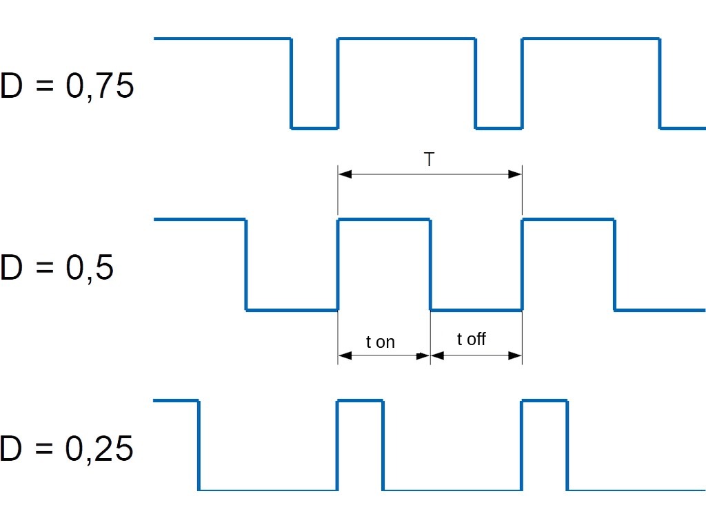
Let’s visualize this with a graph. T is the signal period, t_on is the high-level duration, and t_off is the low-level duration. D is the duty cycle. Suppose the period T is 4 ms, and the high-level duration is 1 ms. In this case, the duty cycle will be:
D = 1/4 = 0.25 or 25%.
If the pulse duration increases to 2 ms, the duty cycle becomes:
D = 2/4 = 0.5 or 50%.
2.Duty Factor
Duty factor is the reciprocal of the duty cycle. They are often confused, but they are not the same. Duty factor is the ratio of the total period of the signal to the duration of the pulse (high level). It is always greater than or equal to 1. Duty factor and duty cycle are often mistaken for one another, but they are distinct concepts. For example, if the pulse duration is 1 ms and the period is 4 ms, the duty factor will be: Duty factor = 4.
3.Resolution
PWM resolution determines how precisely the duty cycle can be controlled, i.e., how smoothly the average value of the output signal can be adjusted. It depends on the bit depth of the timer used to generate the PWM signal. Resolution is measured in bits. The higher the resolution, the smoother and more precise the control. For example, 8 bits allows for 0 to 255 duty cycle levels, 10 bits gives 1024 levels, and 16 bits provides 65536 levels, and so on. However, the higher the resolution, the lower the maximum PWM frequency, as the counter must calculate more values within the same period.
PWM Operating Modes
Normal Mode
The normal PWM mode in STM32 is implemented using a timer in up-counting mode and one of two pulse-width modulation modes — PWM Mode 1 or PWM Mode 2. This mode is commonly used for controlling the brightness of LEDs, motor speed, and other tasks that require generating square pulses with adjustable duty cycle.
In PWM Mode 1, the output signal stays high while the counter value is less than the value set in the compare register (CCR), and then switches to a low level for the remainder of the period, as defined by the auto-reload register (ARR). This provides a direct relationship between the pulse width and the CCR value, allowing for straightforward control of the power delivered to the load. This mode is often referred to as “normal” PWM and is similar to the Fast PWM mode in AVR microcontrollers.
In PWM Mode 2, the output signal remains low while the counter value is less than the CCR, and switches to high once the counter exceeds the CCR value, continuing until the end of the period. This mode can be used when inverted PWM logic is required, for example, to control an active-low input on a device.
Phase-Corrected Mode
The phase-corrected pulse-width modulation mode in STM32 is implemented using the center-aligned timer counting mode. In this mode, the timer counter first increments from zero to the specified auto-reload value (ARR), and then decrements back to zero, forming a symmetric cycle. This structure makes the PWM pulses symmetrical around the middle of the period, reducing electromagnetic interference (EMI) and ensuring even energy distribution.
This mode is particularly useful in motor control systems, power converters, and other applications where signal stability and purity are critical.
Additional PWM Modes
In addition to standard modes, STM32 offers more flexible or specialized PWM operating modes, which are used in more complex scenarios:
- Center-Aligned PWM: This mode provides symmetric pulse shapes by using the timer’s bidirectional counting. It is commonly used in electromechanical drives and power electronics to reduce electromagnetic interference (EMI).
- One-Pulse Mode: This mode generates a single PWM pulse on startup or upon an external event. It is useful for precise positioning or generating single pulses for specific applications.
- Complementary PWM with Dead-Time: Available in advanced timers (such as TIM1, TIM8), this mode allows generating a pair of signals with a delay between their transitions. It is often used for controlling half-bridges and power switches.
- PWM with DMA or Interrupts: This mode allows dynamically changing the duty cycle of the PWM signal without involving the main processor. It is useful in scenarios like generating complex signal patterns or waveform playback.
- Forced Output Modes: These modes enable software control to force the output into a fixed state, regardless of the timer operation. They are used in debugging or emergency situations.
Software Implementation of PWM
Let’s consider one possible method for software PWM implementation on the STM32. We will work with the STM32F4 Discovery board with the STM32F407VGT6 microcontroller.
It’s important to note that this approach is only necessary to better understand how PWM works in its basic mode. In most cases, if hardware PWM is available, it is better to use it, as it utilizes fewer resources of the microcontroller and often provides a higher quality signal.
For software PWM implementation, we will use Timer 2, which is on the APB1 bus. We will use the internal generator with no prescalers, thus achieving a frequency of 16 MHz on the APB1 bus.
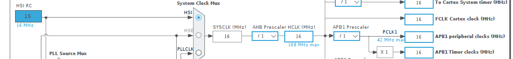
In the timer configuration tab (for the timer 2 in this case), set the Clock Source to Internal Clock.
This setting ensures that the timer will use the internal clock of the microcontroller as its time base, rather than an external clock or other sources. This is important for controlling the timing of PWM signals accurately without relying on external inputs.
![]()
By setting the clock source to Internal Clock, we are defining the frequency of the APB1 bus for our timer. Next, we enable interrupts.

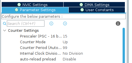
Let’s go to the timer settings under the Parameter Settings tab and review its configuration parameters. Set the following values:
Prescaler 15 – Prescaler (remember to add +1)
Counter Period (ARR) 99 – defines the maximum possible value up to which the timer will count (remember to add +1).
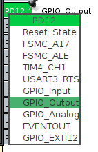
Let’s set PD12 as an output so that the LED connected to this pin can light up.
Calculation
Given:
Timer input frequency: 16 MHz (16,000,000 Hz)
Prescaler: 15
Counter period (ARR): 99
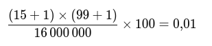
16000000/16*100=1000Hz
The logic of operation is as follows. We need the LED to gradually light up over the course of one second, then turn off, and then light up again over the course of one second. We selected the frequency, prescaler, and counter parameters so that our period T equals 0.01s, i.e., 10ms.
The duty cycle starts at zero. Our local counter is also zero. The timer triggers an interrupt 100 times per period, each time incrementing the counter by 1. When the counter reaches 100, the duty cycle increases by 1, and the counter is reset to zero. Then, the cycle repeats, with the duty cycle increasing by 1 each time, until it reaches 100%, and the LED is at full brightness. After that, the duty cycle is reset to zero, the LED turns off, and the cycle repeats.
Code of the program
After setting all the parameters in the ioc file, we generate the code. Then, we add timer functionality. We’ll start the timer and clear the flag to prevent the timer from triggering immediately.
 /* USER CODE BEGIN 2 */
 __HAL_TIM_CLEAR_FLAG(&htim2, TIM_SR_UIF);
 HAL_TIM_Base_Start_IT(&htim2);
 /* USER CODE END 2 */
Next, we add the duty cycle and counter variables.
/* USER CODE BEGIN PV */
volatile uint8_t
duty_cycle = 0;
volatile uint16_t
counter = 0;
/* USER CODE END PV */
All the work will take place inside the interrupt vector handler.
void HAL_TIM_PeriodElapsedCallback(TIM_HandleTypeDef *htim) {
if (htim->Instance == TIM2) // <span style="font-weight: 400;">We check that it's TIM2</span>
{
if (duty_cycle >= counter) {
HAL_GPIO_WritePin(GPIOD, GPIO_PIN_12, GPIO_PIN_SET);
}
else { HAL_GPIO_WritePin(GPIOD, GPIO_PIN_12, GPIO_PIN_RESET);
}
counter++;
if (counter == 100) {
duty_cycle++;
counter = 0;
}
}
}
As mentioned earlier, the duty cycle counter will reach one hundred over the course of one second, causing the LED to gradually light up to full brightness and then turn off abruptly. The cycle then repeats. This demonstrates that our PWM is functioning correctly and that we have successfully implemented software PWM in practice. Now let’s move on to hardware PWM.
Hardware PWM
Hardware PWM is implemented using timers. To determine which specific timers support hardware PWM, you’ll need to refer to the datasheet for your microcontroller. The timers on your microcontroller include special modes for generating PWM signals without involving the CPU, which minimizes processor load and ensures precise control over signal parameters.
Let’s slightly change our task: in the main loop, we’ll gradually increase the LED brightness by 10% every second. This will demonstrate how PWM can be used to control any device by adjusting the duty cycle.
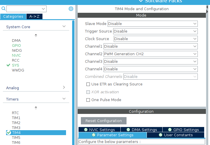
For our example, Timer 4 with Channel 2 is a good choice, as it is connected to one of the onboard LEDs. (We’re still using the STM32F4 Discovery board.) The clock frequency remains 16 MHz. Next, go to the “Timers” tab, find Timer 4, Channel 2, and select “PWM Generation CH2.”
The settings and calculations remain the same: 16 MHz clock frequency, Prescaler set to 15, and Counter Period (ARR) set to 99.
Next, scroll down in the settings to find a very important parameter: Pulse. This defines the pulse width and directly determines the duty cycle. Initially, this value is set to zero. Then, enable timer interrupts.

And we add the timer start command in the code:
/* USER CODE BEGIN 2 */
HAL_TIM_PWM_Start(&htim4, TIM_CHANNEL_2);
/* USER CODE END 2 */
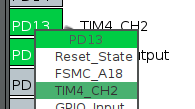
Assign pin PD13 to the corresponding channel of our timer.
Then, in the main program loop, we increase the Pulse value (duty cycle) by 10% every second.
for (uint32_t pulse = 0; pulse <= 100; pulse += 10)
 {
 __HAL_TIM_SET_COMPARE(&htim4, TIM_CHANNEL_2, pulse);
 HAL_Delay(1000);
 }
This gradually increases the duty cycle, making the LED glow brighter until it reaches full brightness.
Pulse Width Modulation (PWM) is a powerful and versatile control method widely used in STM32 microcontrollers. It allows precise regulation of power, brightness, or speed with minimal resource consumption. While a software-based PWM implementation is useful for understanding how PWM works, hardware PWM is always the preferred choice in real-world applications — it’s more reliable, accurate, and does not burden the CPU.