
Clock Configuration tab
In STM32CubeIDE, the Clock Configuration tab in the .ioc file allows you to configure the microcontroller’s clock system. This tab enables you to select the clock source (internal or external oscillator), set bus frequencies (AHB, APB1, APB2), and adjust dividers and multipliers to achieve the desired parameters. With its visual interface and automatic calculations, it simplifies clock configuration, ensuring stable peripheral operation and optimal device performance.
To use it effectively, you need to understand the purpose of each element in this tab. Let’s explore how it works and what features it offers.
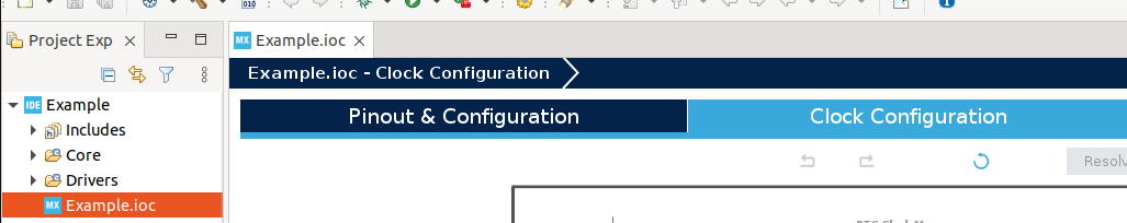
Open CubeIDE, navigate to your project, and open the Project.ioc file. Then, go to the Clock Configuration tab.
You will see a screen like this. The layout varies depending on the microcontroller—in my case, it’s the STM32F407VGT6. For convenience, I’ve marked each element with underlined numbers, though these numbers are not present in CubeIDE itself.
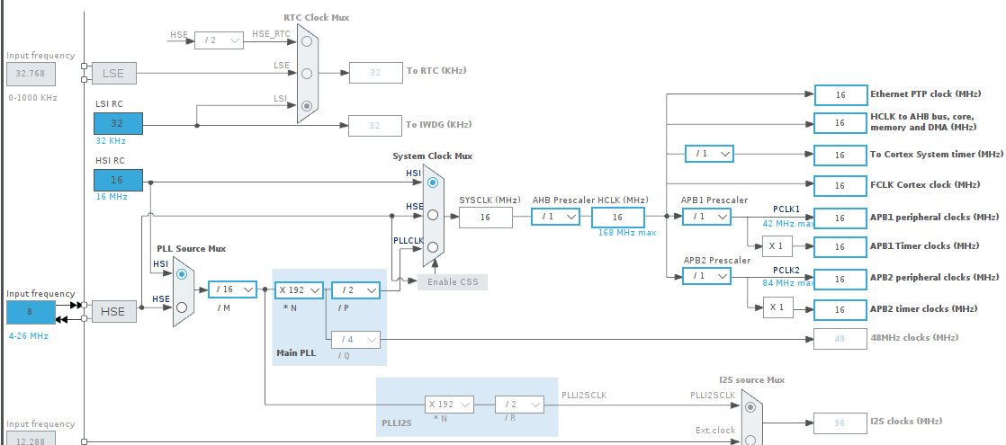
Examining the Low-Frequency Clocking Scheme
1 – Input Frequency: This parameter sets the frequency of the external low-speed crystal oscillator (LSE – Low-Speed External). The LSE operates at 32.768 kHz and is typically used for real-time clock (RTC) operation as well as in certain low-power modes.
2 – LSE (Low-Speed External): A crystal oscillator running at 32.768 kHz. This frequency is a standard choice for RTC operation because it divides by 2¹⁵ to produce 1 Hz (one tick per second).
Configuring the External Clock Source
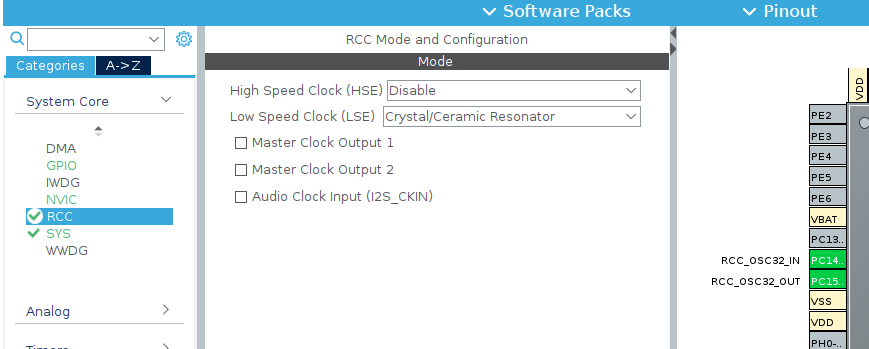
To enable an external clock signal, go to System Core settings, open the RCC tab, and in the Low Speed Clock field, select either Crystal/Ceramic Resonator or BYPASS Clock Source.
- If you are using RTC with a standard 32.768 kHz quartz crystal, select Crystal/Ceramic Resonator.
- If your project requires a custom setup where the clock signal comes from an external generator (e.g., another chip), choose LSE Bypass Clock Source.
When using the bypass mode, the PC14 and PC15 pins become active.
3 – LSI (Low-Speed Internal): An internal low-speed RC oscillator, used as an alternative to the external LSE.
4 – Divided External Crystal Frequency: The clock frequency of the external crystal oscillator (element 8) divided by 2.
5 – RTC Clock Mux: A multiplexer that allows you to select one of several available clock sources for the RTC.
6 – RTC (Real-Time Clock): A built-in microcontroller module designed for real-time tracking, commonly used for timekeeping and low-power applications.
7 – IWDG (Independent Watchdog Timer): A dedicated hardware module that protects the system from crashes or failures. The IWDG operates independently of the main clock system and can reset the microcontroller if the main processor stops functioning correctly.
8 – Input Frequency: The input frequency of the external high-speed crystal oscillator (HSE – High-Speed External). This is commonly used as the primary clock source for the entire system. Compared to the internal oscillator (HSI), HSE offers better frequency stability, which is crucial for precise timing calculations and communication interfaces.
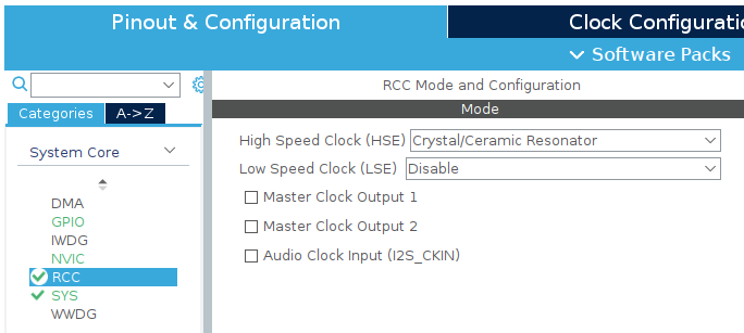
To enable HSE, go to Pinout & Configuration – RCC – HSE, and select Crystal/Ceramic Resonator.
3 – LSI (Low-Speed Internal): An internal low-speed RC oscillator, used as an alternative to the external LSE.
4 – Divided External Crystal Frequency: The clock frequency of the external crystal oscillator (element 8) divided by 2.
5 – RTC Clock Mux: A multiplexer that allows you to select one of several available clock sources for the RTC.
6 – RTC (Real-Time Clock): A built-in microcontroller module designed for real-time tracking, commonly used for timekeeping and low-power applications.
7 – IWDG (Independent Watchdog Timer): A dedicated hardware module that protects the system from crashes or failures. The IWDG operates independently of the main clock system and can reset the microcontroller if the main processor stops functioning correctly.
8 – Input Frequency: The input frequency of the external high-speed crystal oscillator (HSE – High-Speed External). This is commonly used as the primary clock source for the entire system. Compared to the internal oscillator (HSI), HSE offers better frequency stability, which is crucial for precise timing calculations and communication interfaces.
To enable HSE, go to Pinout & Configuration – RCC – HSE, and select Crystal/Ceramic Resonator.
9 – HSE (High-Speed External Clock): The external high-speed clock source for the microcontroller. HSE is typically connected to an external quartz crystal to provide a stable and accurate clock signal for the system.
10 – HSI (High-Speed Internal Clock): The internal high-speed clock source for the microcontroller. Unlike HSE, HSI doesn’t require external components, as it uses a built-in RC oscillator. It has a fixed frequency, starts up quickly, and can be used as the main or backup clock source. However, it’s less accurate than HSE, making it unsuitable for tasks that require high stability.
11 – PLL Source Mux (Phase-Locked Loop): A multiplexer that selects the clock input for the PLL (Phase-Locked Loop). It allows you to choose either HSI or HSE as the input signal for PLL.
12 – /M Frequency Divider: This determines the division factor of the input signal (either HSI or HSE) before feeding it into the PLL.
13 – N Multiplier: This multiplies the output signal after the /M divider, increasing the frequency.
14 – /P Frequency Divider: This divides the result after multiplication, forming the main system clock frequency (SYSCLK).
15 – /Q Frequency Divider: To enable this, you need to activate one of the USB, RNG, or SDIO modules.
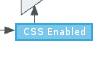
16 – System Clock Mux: This is a multiplexer that selects the main clock source for the system clock frequency (fSYSCLKf). This is a crucial setting, as fSYSCLKf is used for the operation of the processor core. It offers three options for clock source selection: HSI, HSE, or PLLCLK. Additionally, it includes the Clock Security System (CSS), which is designed to automatically switch to a backup clock source in case the primary clock fails. Enabling CSS helps prevent the microcontroller from stopping abruptly if the external quartz crystal (HSE) fails. (To enable CSS, click on the block.)
17 – SYSCLK: The main clock frequency for the microcontroller, buses, and most peripheral devices.
18 – AHB Prescaler: A frequency divider that sets the clock frequency for the AHB (Advanced High-performance Bus) based on the system clock.
19 – HCLK (High-Speed Clock): The clock frequency provided to the high-speed AHB bus.
20 – Ethernet PTP Clock: The clock signal used to support PTP (Precision Time Protocol) for precise time synchronization over Ethernet.
21 – HCLK to AHB Bus, Core, Memory, and DMA: The clock frequency used for the following components:
- Processor core
- High-speed AHB bus
- Memory access (SRAM, Flash)
- DMA (Direct Memory Access)
22 – To Cortex System Timer (SysTick): The frequency supplied to SysTick, the system timer, often used for working with RTOS or precise timekeeping.
23 – FCLK Cortex Clock: The main system clock signal. This setting impacts the performance of the microcontroller, as the processor executes instructions at this frequency.
24 – APB1 Peripheral Clocks: The clock frequency for peripheral devices connected to the APB1 bus (e.g., UART, I2C, SPI, CAN).
25 – APB1 Timer Clocks: Configures the clock frequencies for timers connected to the APB1 bus.
26 – APB2 Peripheral Clocks: The clock frequency for peripheral devices connected to the APB2 bus (e.g., ADC, USART, SPI).
27 – APB2 Timer Clocks: The clock frequency for timers on the APB2 bus.
28 – Frequency for USB, RNG, SDIO: The clock frequency for the USB, RNG, and SDIO modules.
29 – Frequency for I2S Clocks: The clock frequency for the I2S interface. To enable this, you must activate I2S in the Multimedia tab.
30 – N Multiplier for I2S Mux: The multiplier for the I2S multiplexer.
31 – /R Divider for I2S Mux: The divider for the I2S multiplexer.
32 – I2C Source Mux: A multiplexer for I2S, allowing you to choose the clock source.
33 and 34 – MCO Output Multiplexers: MCO stands for Microcontroller Clock Output, and it is a useful feature for diagnostics and synchronization with external devices. In simple terms, this allows you to output a specific clock frequency on a microcontroller pin. This enables you to use the microcontroller’s clock signals for other external devices or for system diagnostics.
We’ve reviewed the blocks presented in the Clock Configuration tab of the .ioc file (for the STM32F407VGT6 microcontroller). This article is particularly helpful for those who have never worked with this tab before, so that when they see all these blocks, they’ll understand what each one does. Of course, as you work with the configuration, you’ll become more familiar with each of them and learn how to set them up correctly.