
Exploring Pinout & Configuration in CubeIDE: Categories and Pinout View in the .ioc File
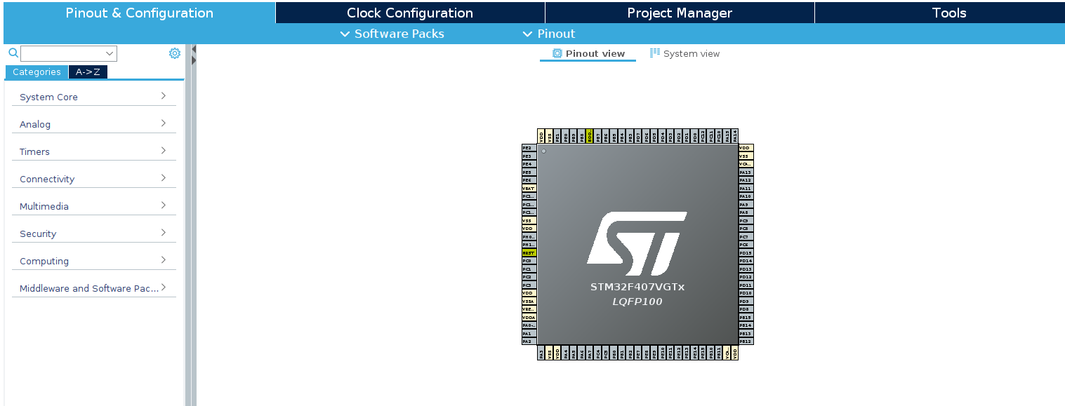
Let’s take a closer look at the Pinout & Configuration panel. Open the ProjectName.ioc file of your project, where you’ll find the tab we’re interested in.
We can divide this tab into two sections: left and right. On the left, you’ll see eight categories: System Core, Analog, Timers, Connectivity, Multimedia, Security, Computing, Middleware, and Software Packs. On the right, you’ll find a visual representation of your microcontroller.
Key Functions of This Tab
- Provides an intuitive graphical interface for visually configuring microcontroller pins and peripheral devices.
- Allows easy setup of peripherals such as UART, SPI, I2C, GPIO, ADC, and more.
- Highlights conflicts if multiple peripherals attempt to use the same pin, helping to avoid configuration errors.
All of this significantly reduces development time, especially in the early stages of a project.
Left Section: Categories
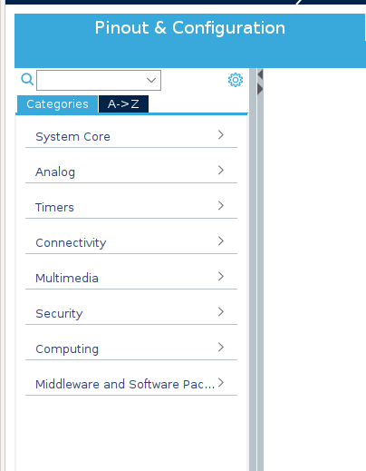
The left section of the Pinout & Configuration tab in STM32CubeIDE contains a structured list of categories for configuring various aspects of the microcontroller. Each category corresponds to a specific group of settings or peripheral devices. The available options depend on the selected microcontroller, but some key elements, such as System Core, NVIC, and RCC, are always present.
As you gain experience with CubeIDE, you’ll naturally become familiar with the purpose of each category. For now, let’s take a look at what they are responsible for.
It’s important to note that this article does not cover every feature of every tab, as their availability varies significantly depending on the STM32 microcontroller model. Instead, we’ll focus on the general principles and core functionalities that are common across most STM32 devices.
System Core
- DMA (Direct Memory Access) – Allows peripherals (such as UART, ADC, SPI) to transfer data to and from memory without CPU involvement, reducing processor load during data transfers. Ideal for handling large data volumes or frequent transactions.
- GPIO (General-Purpose Input/Output) – Configures microcontroller pins for digital input or output. Essential for controlling external components and reading sensor signals.
- IWDG (Independent Watchdog Timer) – A failsafe mechanism that resets the microcontroller if the program becomes unresponsive, ensuring system reliability. Your best friend in preventing crashes—it will save your project more than once.
- NVIC (Nested Vectored Interrupt Controller) – Manages system interrupts and their priorities. It handles events such as incoming UART data or ADC conversion completion, ensuring proper sequencing when multiple interrupts occur simultaneously.
- RCC (Reset and Clock Control) – Controls the clock settings for all microcontroller modules and external peripherals.
- SYS (System Configuration) – Handles system functions such as debug interface configuration and memory management.
- WWDG (Window Watchdog Timer) – A more advanced watchdog timer that allows defining a specific “window” in which the system reset must be triggered, preventing both early and late resets.
Analog
- ADC (Analog-to-Digital Converter) – Converts analog signals into digital data for microcontroller processing. Used for measuring battery voltage, reading potentiometer values, and other sensor applications.
- DAC (Digital-to-Analog Converter) – Converts digital data into an analog signal, useful for generating waveforms, audio signals, and analog control voltages.
Timers
- RTC (Real-Time Clock) – A dedicated module for keeping track of date and time. It remains operational even when the main power is off if a backup battery is connected.
- TIM (Timers) – General-purpose and advanced timers used for various timing operations, including PWM generation, event counting, and time delays.
Connectivity
- CAN, UART, SPI, I2C, USB, and others – Communication interfaces that enable interaction with external devices, sensors, and other microcontrollers. Each of these will be covered in separate articles.
Multimedia
- DCMI, I2S, and others – Peripherals designed for handling multimedia data, including image capture, sound processing, and video streaming.
Security
- RNG (Random Number Generator) – A module used for generating random numbers, crucial for cryptography, security protocols, and other randomness-dependent tasks.
Computing
- CRC (Cyclic Redundancy Check) – Used for verifying data integrity during transmission or storage. Ensures data reliability by detecting errors in communication interfaces.
Middleware and Software Packs
This section provides access to additional software components and libraries that can be integrated into your project. For example:
- FreeRTOS – A real-time operating system (RTOS) designed for task, memory, and resource management.
- USB Host/Device – Drivers for working with USB peripherals.
- Sensor Drivers – Software libraries for interfacing with various sensors.
- Artificial Intelligence – Libraries and frameworks for integrating AI into your application.
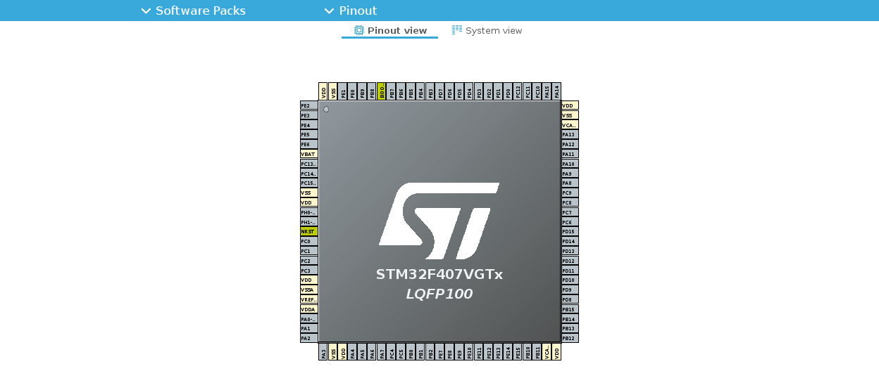
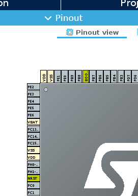
Right Section: Pinout View
Now, let’s take a look at the right section, which appears as follows:
If you left-click on a pin of the microcontroller, a list of possible states for that pin will appear. The available options will vary for each pin, depending on the internal configuration of the microcontroller. For example, it might look like this:
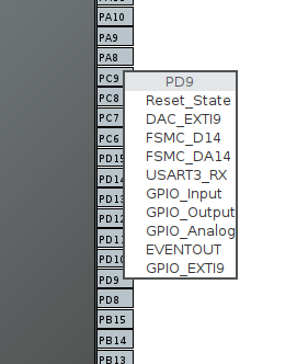
For convenience, we can categorize all the pins into several groups.
- Universal GPIO (General Purpose Input/Output) – Basic digital and analog functions (GPIO_Input, GPIO_Output, GPIO_Analog). This group includes pins that can be configured as general-purpose inputs/outputs. They are used for basic tasks such as reading buttons, controlling LEDs, or interfacing with digital devices.
- Peripheral Functions (Alternate Functions) – Pins that can be configured to work with the microcontroller’s peripheral devices, such as UART, SPI, I2C, timers, and others (e.g., USART_TX, SPI_MOSI, TIM_CH1).
- System Functions – This group includes pins that are essential for the basic operation of the microcontroller and its interaction with external components (e.g., power pins like VDD, VSS, VDDA, VSSA, and OSC_IN, OSC_OUT for connecting a crystal oscillator).
- Additional Functions – This group includes specialized pins that support unique functions, available only in certain microcontroller models (e.g., USB_DM, USB_DP, CAN_TX, I2S, SAI).
Pin Color Coding
In STM32CubeIDE, the color coding of the pins plays a crucial role in enhancing the usability of the microcontroller configuration. Different colors help quickly identify which pins are in use, which are reserved, and which are used for power or control. This visual representation allows for easy analysis of the chip’s configuration, helping to avoid mistakes during the design phase.
You can view and change the pin colors in the Pinout → Pinout View Colors tab, located just above your microcontroller.
Standard Pin Colors
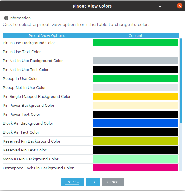
In the Pinout View Colors section, you can customize the background and text colors of pins in different states: used, unused, locked, reserved, etc. This allows you to make important pins more noticeable or choose contrasting colors for better readability. Let’s go over some of the most commonly used standard colors.
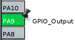
Pin In Use
A pin that is actively used in the project and serves a specific function, such as an input, output, or peripheral connection (UART, I2C, SPI, etc.). These pins are colored green, indicating their active role in the circuit.
Pin Not In Use
A pin that is available but has not yet been assigned to any function. It is visually highlighted in gray, making it easy to identify free pins.
Pin Power
Pins through which the microcontroller receives power (VDD, VSS, GND, etc.). These pins are colored light yellow, making them easily recognizable among other pins.

Reserved Pin
Pins that are not used in the current configuration but are reserved by the system or the user. These pins are colored yellow-green, distinguishing them from simply unused pins.

Pin Single Mapped
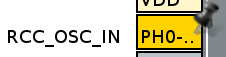
A pin assigned to only one function with no alternative usage. It is colored yellow, making it easy to quickly identify pins with a fixed functionality.
That’s all for now. This article serves more as an introduction, and of course, each device and pin should be explored individually. I would like to emphasize that the Pinout & Configuration tab is a powerful tool for configuring the microcontroller, making it an indispensable resource for both beginners and experienced developers.