

External Interrupts
Let’s take a closer look at an essential feature of microcontrollers — interrupts. We’ll go over the different types, how to use them, and then try out an external interrupt in a practical example.
Interrupts are a mechanism that responds to events occurring within a microcontroller. When such an event happens, the program saves its current position in the main loop and jumps to a special interrupt handler, known as a vector. Once the interrupt handler finishes executing, the program returns to the exact point in the main loop where it left off.
It’s important to distinguish between an event and an interrupt: an event triggers an interrupt, and the interrupt then performs a specific set of actions in response.
Interrupts are used throughout a microcontroller system—for example, to respond to a button press, to handle timers, communication interfaces, and more.
Types of Interrupts.
STM32 microcontrollers support external, internal, and system interrupts.
External interrupts (EXTI) are triggered by changes on GPIO pins—such as a button press or a sensor activation.
Internal interrupts are generated by the microcontroller’s own peripherals, like timers, UART, ADC, and others, and typically indicate the completion of an operation or the occurrence of a significant event.
System interrupts are built into the Cortex-M core and provide essential functionality for the system itself, including the runtime environment of the microcontroller.
NVIC Module
In STM32 microcontrollers, interrupt management is handled by a dedicated module called the NVIC (Nested Vectored Interrupt Controller). It allows you not only to enable or disable specific interrupts but also to assign priorities, so that more critical events can interrupt less important ones. Thanks to the NVIC, the microcontroller supports nested interrupt handling—an interrupt can itself be interrupted if a higher-priority one occurs.
Configuration is typically done using convenient HAL functions like HAL_NVIC_SetPriority() and HAL_NVIC_EnableIRQ(). For more fine-grained control, you can use the CMSIS framework or the low-level (LL) library.
The Concept of an Interrupt Vector
Every interrupt has its own interrupt vector. An interrupt vector is essentially a pointer to the function that the microcontroller should call when a specific interrupt occurs.
When an interrupt is triggered, the STM32 looks up a special structure called the interrupt vector table to determine which handler function to execute.
For example, the STM32F407VGT6 microcontroller supports 82 different interrupt vectors. All of them are listed in its reference manual. Below, I’ll show a small portion of that table.
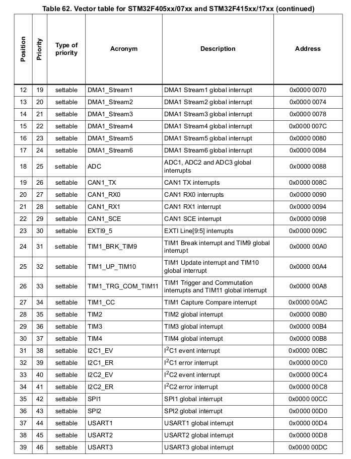
The table columns typically include the interrupt number, name, description, the address of the vector, and the priority level.
Interrupts have priorities ranging from 15 to 0, where 15 is the lowest and 0 is the highest priority. If an interrupt with a higher priority is triggered while another is being handled, the microcontroller immediately switches to the new, higher-priority interrupt. If the new interrupt has a lower priority, it will wait until the current one finishes.
In our case, we can set the interrupt priority programmatically using values from 0 to 15.
Steps for Working with Interrupts
- Enable global interrupts.If you’re using the HAL library, this is done automatically inside the HAL_Init() function.
- Configure the peripheral (e.g., a timer) to work with interrupts.
- Enable the specific interrupt for that peripheral.
- Create an interrupt handler function in your program code.
External Interrupts: Button Press Example
Let’s take a look at how external interrupts work using the STM32F4 Discovery board, which is based on the STM32F407VGT6 microcontroller. This board conveniently includes an onboard LED and push button, making it ideal for our example.
Here’s the logic:
When the button is pressed, an external interrupt is triggered. Inside the interrupt handler, we record the current state of the button. Then, we start a timer set for 10 milliseconds. Once the timer interrupt fires, we check the button state again. If it’s still the same, we toggle the LED.
This approach helps protect against accidental presses and debounces the button input.
Let’s go through the setup steps. We’ll do everything in CubeIDE. First, open the .ioc file of your project.
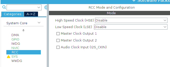
1.We will use the internal crystal oscillator.
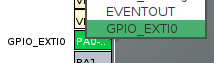
2.According to the schematic, the button is connected to pin PA0. Let’s configure it for external interrupts. To do this, click on the pin and select GPIO_EXTI0.
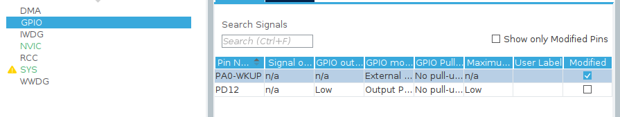
3.In the GPIO tab, select the row with the pin. Enable the trigger on the rising edge. Set the GPIO mode to External Interrupt Mode with Rising Edge.
4.In the NVIC tab, enable interrupts for our EXTI line 0.
![]()
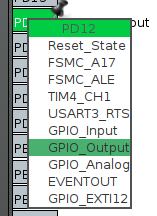
5.Let’s configure the onboard LED as an output. We’ll use PD12, which is a green LED.
6.Let’s configure our timer. You can find more details about timers in this article (link to the article about timers). I’ve chosen Timer 2, but in this case, it’s not critical—you can choose any timer.
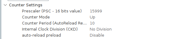
These settings ensure that with a 16 MHz frequency, the timer will overflow after 10 ms.Don’t forget to enable the timer interrupt.
![]()
We’re done with the settings. Let’s move on to the code. We’ll define a variable to store the button state.
/* USER CODE BEGIN PV */
volatile uint8_t button_state_snapshot = 0;
/* USER CODE END PV */
Next, we are interested in two functions. The first is the interrupt handler function for the external interrupt.
void HAL_GPIO_EXTI_Callback(uint16_t GPIO_Pin)
 {
 if (GPIO_Pin == GPIO_PIN_0) //Check the PA0 button
 { button_state_snapshot = HAL_GPIO_ReadPin(GPIOA, GPIO_PIN_0);
 __HAL_TIM_SET_COUNTER(&htim2, 0); // Reset the counter
 HAL_TIM_Base_Start_IT(&htim2); // Start the timer with an interrupt
 }
}
In this function, we check if the button we’re interested in is actually pressed, record its state, and start the timer.
Next, we’ll look at the timer interrupt handler function.
void HAL_TIM_PeriodElapsedCallback(TIM_HandleTypeDef *htim) {
    if (htim->Instance == TIM2) {
        uint8_t current_state = HAL_GPIO_ReadPin(GPIOA, GPIO_PIN_0);
        if (current_state == button_state_snapshot && current_state == GPIO_PIN_SET) {
            HAL_GPIO_TogglePin(GPIOD, GPIO_PIN_12);
    }
    HAL_TIM_Base_Stop_IT(&htim2); // Stop the timer.
}
}
In this function, we read the current state of the button, and if it’s the same as before, we toggle the LED. If you need faster button response, you can decrease the timer’s duration.
That’s all for this example. Here, we’ve gone over the principles of working with interrupts and applied them to control an LED.