

DMA is a hardware module in STM32 microcontrollers that allows peripheral devices to exchange data with memory without involving the processor (CPU). This frees the processor from performing routine data transfer tasks, improving overall system performance. It effectively allows the program to run in parallel, with the CPU handling its tasks while the DMA handles its own.
It’s important to understand that DMA is tied to specific hardware in your microcontroller. In other words, each DMA module has a fixed connection scheme to the peripherals. This means that not every DMA channel can service just any UART, SPI, or ADC — there is a strict mapping. For example, DMA1 Channel 5 may handle USART1_RX. These connections are defined inside the chip and cannot be changed through software.
DMA architecture.
STM32 microcontrollers have one or more built-in DMA (Direct Memory Access) controllers, depending on the series and model. Each controller consists of several independent channels or streams that can operate in parallel. The number of controllers, channels, and their capabilities (such as priorities, supported modes, and request sources) are specified in the documentation for the specific microcontroller.
In DMA, there are concepts of channels and streams, and it’s important not to confuse them. A stream is a physical block of the DMA controller that performs data transfers, and each stream can be used for independent data transfers.A channel is a logical multiplexer/router that connects a peripheral request to a specific stream. Using a channel, we select which peripheral to work with, while the stream performs the actual DMA operation.Channels are tied to specific sources (peripheral devices). Each peripheral device is associated with a specific DMA channel and stream.
For example:
- ADC1 can use DMA2, Stream 0, Channel 0.
- USART2_TX can use DMA1, Stream 6, Channel 4.
- SPI1_RX can use DMA2, Stream 2, Channel 3.
Each DMA channel can be assigned one of four priority levels (Very High, High, Medium, Low) to manage conflicts between channels.
A channel is tied to a specific peripheral, while streams are independent hardware resources of the DMA. This means that a single channel can be used by different DMA streams, but at any given time, only one stream can operate with that channel.
Operating modes
DMA has two operating modes: memory-to-memory and memory-to-peripheral (and peripheral-to-memory).
Memory-to-memory
In this mode, the DMA copies data from one memory area to another without involving any peripheral. Both the source and the destination are located in SRAM, Flash, or another memory address space. This mode is convenient for quickly copying large amounts of data.
Memory-to-peripheral and peripheral-to-memory
A key point for understanding DMA operation is that all transfers occur via requests. When transferring data to a device (UART, SPI, etc.), the DMA sends a request to the device, and if it receives a positive response, the DMA begins the data transfer. In the peripheral-to-memory case, the DMA waits for a request from the device and then starts transferring data from the device to memory.
DMA Interrupts
There are three types of interrupts in DMA:
- Transfer Complete (TC) — Triggered when the entire specified data volume has been transferred. This is typically used to know that the copying is finished and the data can now be processed.
- Half Transfer Complete (HT) — Triggered when half of the buffer has been transferred. This is very useful for processing data “on the fly” while the second half is still being filled. For example, with a circular buffer from an ADC or UART, you can process half of the transfer at a time, enabling continuous and fast data handling.
- Transfer Error (TE) — Triggered when a transfer error occurs.
Memory-to-Peripheral Example
Let’s create a hardware PWM using DMA to smoothly fade an LED.
Here’s the working idea. As we know, all DMA operations are request-driven. We need to change the duty cycle of our PWM, so we configure it so that the PWM block sends a request to the DMA, which then provides the value that will determine the duty cycle. The request to the DMA block is sent at the capture/compare event — all this happens without CPU involvement.
We’ll use Timer 4, Channel 1, on pin PD13. On our board, this is the green LED. The APB1 bus for the timer is set to 16 MHz.
Configuring the PWM:
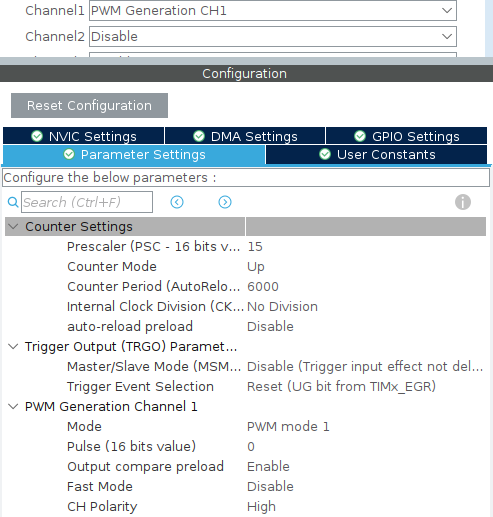
In the timer settings, select PWM Generation CH1 to generate hardware PWM and apply the following settings:
- Prescaler: 15
- Counter Period: 6000
- Pulse: 0
Configuring DMA
Click on DMA Settings for our timer TIM4.
![]()
Add a DMA request. Click the Add button. Select DMA Request — TIM4_CH1.
Set Stream to DMA1 Stream 0 and Direction to Memory to Peripheral.Here’s what happens next.
When you select TIM4_CH1, you use DMA to automatically update the CCR1 register (Capture/Compare Register 1), which determines the pulse width (high-level duration) of the PWM signal on Channel 1 — in other words, the Pulse value.
- The timer counts from zero to ARR (Counter Period).
- When the timer counter reaches the CCR value, an event is triggered, generating a request to the DMA.
- The DMA writes a new value into the CCR (Pulse).
- The timer continues counting to ARR (Counter Period).
- The process repeats with the updated CCR (Pulse) value.
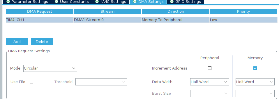
Stream DMA1 Stream 0. This selects the stream. For TIM4_CH1, only one stream is available: DMA1 Stream 0.
Direction Memory to Peripheral. We select Memory to Peripheral because we are transferring data from memory to the peripheral (the TIM4_CCR1 register).
Priority – Low. The priority determines the importance of this DMA stream relative to other DMA streams. Leave it as Low.
Mode – Circular. In Circular mode, the DMA automatically starts a new transfer after completing the previous one without needing to be restarted.
Increment Address – Memory. This allows the DMA to work with arrays, transferring data sequentially from each memory cell. Enable this when working with an array. If sending a single constant value, select Peripheral instead.
FIFO – Disabled. FIFO (First-In-First-Out) is a memory buffer inside the DMA controller that temporarily holds data before transfer. It is useful for large data volumes.
Data Width – Half Word. The TIM4_CCR1 register is 16-bit, and Half Word is used when the peripheral (e.g., a timer or peripheral register) works with 16-bit data. In our case, the value ranges from 0 to 6000.
We have the following settings:
Now we need to fill an array with the pulse width values that we will transfer.
void Fill_PWM_Values() {
int index = 0;
// Increasing brightness (от 0 до MAX_PULSE)
for (uint16_t pulse = 0; pulse <= MAX_PULSE; pulse += STEP) {
pwm_values[index++] = pulse;
}
// Decreasing brightness (от MAX_PULSE до 0)
for (uint16_t pulse = MAX_PULSE; pulse > 0; pulse -= STEP) {
pwm_values[index++] = pulse;
}
}
MAX_PULSE is the maximum pulse length, equal to the period. In our case, it is 6000.
Start the PWM:
HAL_TIM_PWM_Start_DMA(&htim4, TIM_CHANNEL_1,(uint32_t *)pwm_values, ARRAY_SIZE);
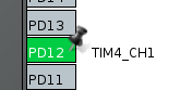
Define PD12 as the output for TIM4_CH1.
As a result, the PWM pulse length changes according to the values in the pwm_values array. This is clearly seen on our LED, which gradually brightens and dims — all without any involvement from the CPU.
Memory-to-Memory Example
Let’s perform a memory-to-memory copy using an array of numbers and then display this array on the screen.
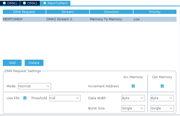
Open the System Core tab -> DMA -> MemToMem.
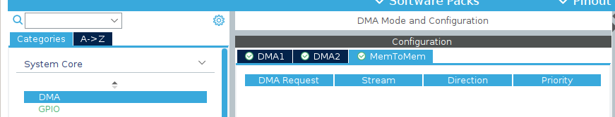
Click the Add button and select MEMTOMEM. Then choose a free stream and configure its settings:
- Mode — Normal
- Increment Address — Enable increment for both source and destination addresses after each element transfer. Since we are transferring an array, this is needed.
- Use FIFO — Enabled, to increase transfer speed
- Threshold (buffer size) — Leave at Full
- Data Width — Byte, since we are transferring numbers from 0 to 100, which fits in one byte
- Burst Size — Single
Enable interrupts.
![]()
Program Code
Create two arrays: fill the first one with values and leave the second one empty. Populate the first array with numbers.
void fillStartArr() {
for (uint8_t i = 0; i < ARRAY_SIZE1; i++) {
arrToDMA[i] = i; // fill it with values from 0 to 99.
}
}
Register a callback that will be triggered upon completion of the memory-to-memory transfer.
HAL_DMA_RegisterCallback(&hdma_memtomem_dma2_stream0, HAL_DMA_XFER_CPLT_CB_ID, dma_m2m_callback);
1)&hdma_memtomem_dma2_stream0 – a pointer to the DMA_HandleTypeDef structure that describes your specific DMA stream/channel.
2)HAL_DMA_XFER_CPLT_CB_ID – a special enum indicating which event the callback is registered for. In our case, it’s the transfer completion.
3)dma_m2m_callback – a pointer to your handler function, which will be called when the event occurs.
It’s important that the callback is registered before starting the DMA.
Let’s write a short handler function.
void dma_m2m_callback(DMA_HandleTypeDef *hdma)
{
dmaTransferComplete = 1;
}
In the handler function, set a transfer-complete variable to 1.
Then start copying from one array to the other.
if (HAL_DMA_Start_IT(&hdma_memtomem_dma2_stream0,
(uint32_t)arrToDMA,
(uint32_t)recArrToDMA,
ARRAY_SIZE1) != HAL_OK)
{
Error_Handler();
}
Then, in a while loop, check the dmaTransferComplete variable, and if it equals 1, call the function to display the array on the screen.
while (1) {
if (dmaTransferComplete) {
HAL_Delay(1000);
sendArrNumber(counter);
counter++;
}
/* USER CODE END WHILE */
/* USER CODE BEGIN 3 */
}
Function body
void sendArrNumber(loc_counter) {
char buffer[10];
sprintf(buffer, "%d", arrToDMA[loc_counter]);
ST7735_DrawString(0, 3*10, buffer, Font_11x18, ST7735_GREEN, ST7735_BLACK);
}
As a result, we filled the second array with data using DMA. Meanwhile, the program code continued executing in parallel with the data transfer, which is very convenient, especially when handling large amounts of data.