

CAN – Controller Area Network
The CAN bus is an industrial serial communication protocol developed by Bosch in the 1980s for automotive electronics. Today, it is used not only in vehicles, but also in industrial automation, medical equipment, robotics, and other fields.
Data transmission over the CAN bus is highly reliable because it features built-in error checking, and the data lines use twisted-pair wiring, meaning that even if exposed to magnetic interference, the final signal remains unchanged. The CAN bus is a multi-node network, and unlike other interfaces, it has no master or slave devices. Instead, it operates on a multi-master principle: any device (node) can begin transmission at any time. To resolve collisions, arbitration based on the message identifier is used — we will discuss this a bit later.
Physical layer of the CAN bus.
Let’s figure out what exactly we need to connect to a CAN bus.
Suppose you have several devices and you want to connect them via CAN.
For this, we will need:
- The device itself — this can be a microcontroller, a sensor, an Arduino, etc. It processes data and decides when to send or receive.
- A CAN controller — it forms and parses frames, handles arbitration and errors.
- A transceiver — a chip that converts the CAN controller’s logical TX/RX levels into a differential signal on the CANH/CANL lines.
- A twisted-pair cable.
- Two terminators (120 Ω resistors).
That’s basically the whole set. Only two resistors are needed for the entire line, and they must be 120 Ω. The rest of the hardware (microcontroller, CAN controller, transceiver) is required individually for each node.
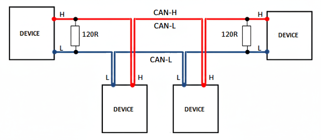
The connection diagram is as follows.
All devices (ECUs, sensors, controllers) are connected to two main lines: CAN_H (High) and CAN_L (Low). Each node has a transceiver connected to these two lines. In other words, we effectively get a parallel connection.
Now a few words about the CAN controller and transceiver.
The CAN controller is the brain responsible for handling the CAN protocol. Its main task is to manage data exchange so that only the relevant data reaches your device, while it takes care of all the rest. It forms and receives frames, checks data integrity, participates in arbitration if conflicts occur, and handles retransmission in case of errors. There are two types: internal (or built-in) and external. For example, the STM32F407 has an integrated CAN controller. In contrast, the Arduino Uno does not have a built-in controller, so an external one, such as the MCP2515, must be used.
The transceiver is a chip that converts the digital signals from the CAN controller into differential signals transmitted over the twisted pair. In other words, it converts the CAN controller’s levels (TXD/RXD) to the CAN bus lines (CAN_H/CAN_L).
What does converting to a differential signal mean? Suppose the CAN controller outputs a 1. For the transceiver, this is a recessive bit, and it sets CAN_H to 2.5 V and CAN_L to 2.5 V. The signal is differential, meaning the voltage is considered as the difference between the two lines: 2.5 − 2.5 = 0 V.
If the CAN controller outputs a 0, this is a dominant signal, and the transceiver sets CAN_H to 3.5 V and CAN_L to 1.5 V. The differential voltage is 3.5 − 1.5 = 2 V.
The transceiver also provides protection against short circuits and static discharge.
The CAN bus has a fairly high speed, which depends on the distance over which the signal needs to be transmitted. Typical values for a standard CAN bus (CAN 2.0) are:
- 1 Mbit/s: Maximum bus length is approximately 40 meters.
- 500 kbit/s: Maximum length increases to 100 meters.
- 125 kbit/s: Length can reach 500 meters.
- 10 kbit/s: At this low speed, the range can reach 1000 meters.
Connectors
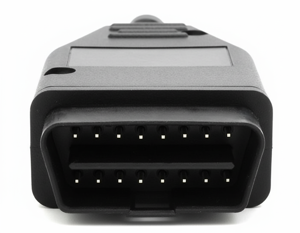
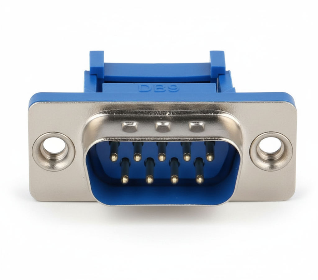
For connecting to a CAN bus in cars, the most common solution is the OBD-II connector (also known as the diagnostic DLC), which has become a standard and is used in almost all modern vehicles for diagnostics and data exchange with electronic control units. In industrial automation and equipment, the D-Sub 9 (DB9) connector is much more common, as specified in CANopen and DeviceNet standards. However, it should be understood that connector choices in different CAN bus applications are not limited to these options. There are many other types of connectors, ranging from sealed industrial M12 and convenient RJ45, to simple terminal blocks and pin connectors used in prototyping and development. Thus, the CAN standard defines only the electrical signals and network topology, while the specific connector type depends on the application area and requirements for reliability, convenience, or connection protection.
OBD connector
D-Sub 9 connector
Frame format
In the CAN bus, data exchange is organized in frames. Each frame has a strictly defined structure and purpose. The CAN standard defines four types of frames.
Data Frame.
This is the main type of frame, used by nodes to transmit useful information.
It consists of:
Start of Frame (SOF): One bit that signals the beginning of a new frame.
Arbitration field: Identifier (11 or 29 bits, depending on the format) + RTR (Remote Transmission Request) bit.
Control field: Indicates the length of the data.
Data field: Up to 8 bytes of data (in classical CAN). In CAN FD, up to 64 bytes.
CRC field: Checksum.
ACK field: Acknowledgment by other nodes.
EOF: 7 bits signaling the end of the frame.
Remote Frame
Used to request data from another node. Here’s how it works: the node that needs data (for example, temperature readings) sends a remote frame on the bus with an identifier corresponding to the required data. The receiving node, which has the requested data and is configured for that identifier, recognizes the request, reads it, and automatically responds by sending a data frame with its data field containing the requested information (for example, the current temperature value).
Structurally, it is almost identical to a data frame, but with one key difference: it has no data field, and the RTR (Remote Transmission Request) bit is set to the dominant state (logical 0).
Error Frame
If one of the nodes detects a frame format violation, it generates and sends an Error Frame onto the bus, which has the highest priority. Upon receiving this frame, the other nodes understand that an error has occurred on the network, and the last transmitted frame must be considered invalid.
Overload Frame
It is used to temporarily delay the transmission of the next frame.
It is employed by nodes that, for some reason, cannot process data in time. In practice, it is rarely used.
Both the Error Frame and the Overload Frame are generated by the node’s CAN controller hardware.
Addressing.
The key principle of CAN bus addressing is that devices on the network do not have addresses. Instead, each transmitted message uses a unique ID (identifier). The ID carries semantic meaning; for example, ID 0x123 might represent “wheel speed,” while ID 0x456 could represent “engine temperature.” All messages transmitted over the CAN bus are broadcast. This means every node on the network “hears” all frames. If a frame with a relevant ID appears on the bus, multiple devices can receive and process it simultaneously, as they are configured to handle frames with that specific ID.
There are two types of IDs: standard — 11 bits (2048 devices) and extended — 29 bits (over 500 million devices).
Arbitration.
Arbitration in the CAN bus is the process of resolving conflicts when two or more nodes attempt to transmit data simultaneously. It is based on the principle of dominant and recessive bits and ensures that only the highest-priority message is successfully transmitted.
The entire system relies on the identifier. Suppose two nodes start transmitting at the same time. Their identifiers are compared bit by bit. As soon as one message has a dominant bit (logical 0) while the other has a recessive bit (logical 1), the second device stops transmitting its message and listens to the first device. For example, 0001 wins over 0010 because the dominant bit comes before the recessive one.
All of this occurs without data loss, as the losing nodes do not lose their data. The CAN controller of each node handles this process.
Practical implementation of a CAN bus.
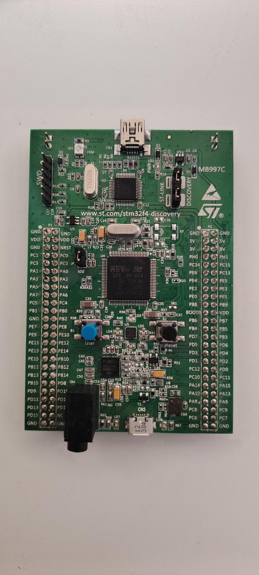
Let’s move on to the practical implementation. There is a Discovery board with an STM32F407VGT6 microcontroller and an Arduino Uno board. Our task is to transmit data from the Arduino Uno and receive it on the STM32 via the CAN bus.
For this, we will need:
STM32F4 Discovery
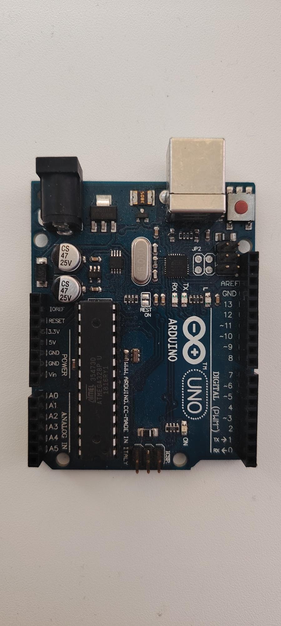
Arduino UNO
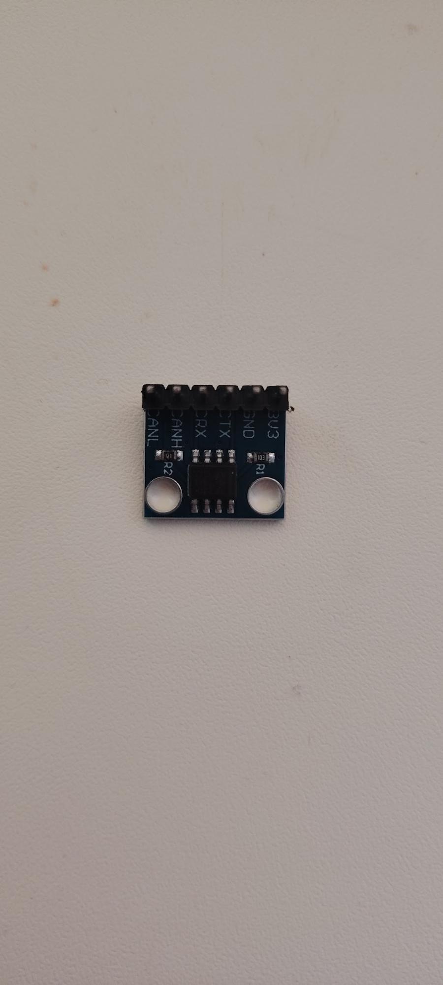
WCMCU-230
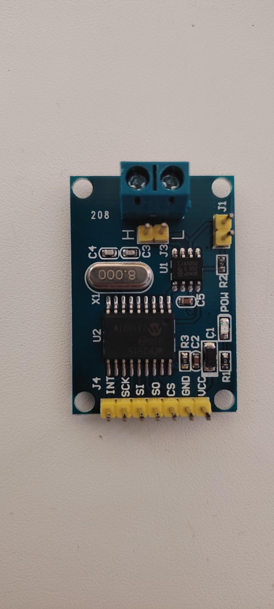
MCP2515
Two 120 Ω resistors.
Twisted-pair wires, but in our case, any wires can be used since the distance is very short.
The STM32F4 microcontroller already contains a built-in CAN controller, but a transceiver is required to work with the CAN bus. The WCMCU-230 is a CAN bus transceiver module based on the SN65HVD230 chip. It acts as a physical interface, converting the CAN controller’s logic signals to the differential signals of the CAN bus.
On the Arduino side, it’s a bit more complex. There is no built-in CAN controller, so we need an MCP2515 board. This is a standalone CAN controller developed by Microchip. It handles all CAN bus logic tasks (frame formatting, ACK, CRC, arbitration, etc.). The board also includes a TJA1050 transceiver to convert logic levels into the differential signals of the CAN bus. The MCP2515 board connects to the Arduino Uno via the SPI interface.
Connection diagram.
Connecting the STM32 to the WCMCU-230.
Open the Connectivity → CAN1 tab. Pins PA11 and PA12 are highlighted, but here we encounter a problem: they are not available on our board, as they are not exposed to external pins. Therefore, we need to manually select other pins, performing a remapping. We choose PB8 (CAN_TX) and PB9 (CAN_RX). CubeIDE allows this manual remapping.
Connect the STM32F4 Discovery board to the WCMCU-230 as follows:
- PB8 (CAN_RX) → CRX
- PB9 (CAN_TX) → CTX
Connecting the Arduino Uno to the MCP2515:
- D11 → SI
- D12 → SO
- D13 → SCK
- D2 → INT
- D10 → CS
There is a very important point here. The MCP2515 board requires a stable 5 V power supply. While the Arduino can provide this voltage, it will not work reliably. Therefore, always power your board from a separate power source.
The second important point is the common ground. The CAN bus operates with a differential signal, and without a shared ground, data transmission will most likely fail.
Next, connect the MCP2515 to the WCMCU-230 using two wires: CAN_H and CAN_L, respectively.
CubeIDE settings.
Let’s calculate the required speed settings. We need to achieve a speed of 20 kbit/s.
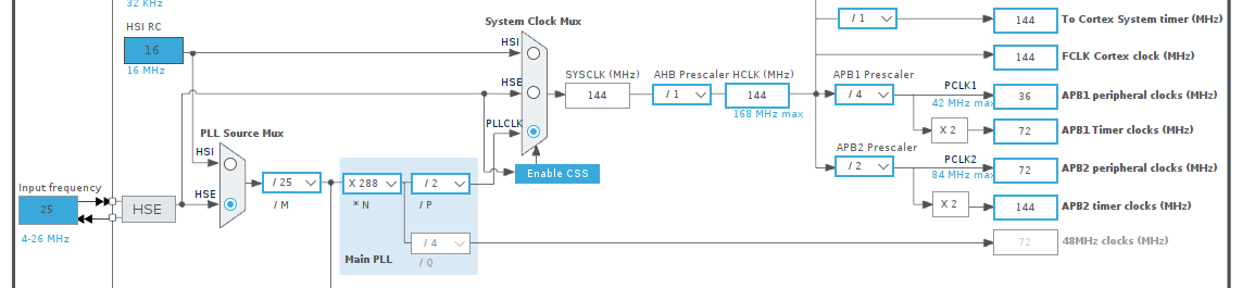
First, go to the Clock Configuration in CubeIDE. The CAN1 module is connected to the APB1 peripheral clock. We need to set its frequency to 32 MHz. To do this, select the external high-speed clock source (HSE).
Next, in the PLL, we need to obtain 144 MHz from a 25 MHz input frequency. Set the following parameters:
PLLM = 25
PLLN = 288
PLLP = 2
Next, set the AHB prescaler = 1 and finally APB1 prescaler = 4, which will give us 36 MHz on APB1.
Next, enable CAN in CubeIDE and set the following configurations.
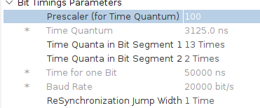
The first thing we need to configure is the Time Quantum (TQ). Time Quantum is the smallest unit of time used to measure the duration of different bit segments in the CAN protocol. Think of a bit as a segment divided into very small, equal-length “steps” or “quanta.” These “steps” are the Time Quanta. Each bit on the CAN bus is divided into several segments, each consisting of a certain number of Time Quanta.
Calculating it is quite simple. Divide the bus frequency by the prescaler. In our case:
32,000,000 / 100 = 320,000
Then we get:
TQ = 1 / 320,000 = 3.125 µs
The bit is divided into three parts.
- SyncSeg (1 TQ) – always 1 quantum. It handles synchronization on the leading edge.
- Time Quanta in Bit Segment 1 (TS1) – the number of TQs in the first segment (includes the Propagation Segment, which compensates for signal delay, plus Phase Segment 1).
- Time Quanta in Bit Segment 2 (TS2) – the number of TQs in the second segment (Phase Segment 2).
Set TQ1 = 13 and TQ2 = 2. These values are obtained from the formula:
N = 1 + TQ1 + TQ2
We get 16, since at a frequency of 32 MHz and a prescaler of 100, this gives exactly 20 kbit/s.
When choosing these values, the sample point (SP) must also be considered. It is calculated using the formula:
SP = (1 + 13) / 16 = 87.5 %
87.5 % means the signal is sampled closer to the end of the bit interval, which is usually good for stable operation at low speeds.
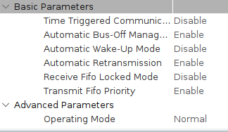
Let’s go over the next block of settings.
Time Triggered Communication Mode – CAN controller mode for adding time-based synchronization.
Automatic Bus-Off Management – setting to return a node to operation after exceeding the error count. Each node has an error counter, and if it is exceeded, the node drops off the bus. This setting allows it to automatically resume operation after a certain period.
Automatic Wake-Up Mode – mode in which the STM32 CAN controller automatically wakes up from sleep when bus activity is detected. This system helps save energy.
Automatic Retransmission – when enabled, forces the controller to resend frames if transmission fails.
Receive FIFO Locked Mode – setting related to the RX_FIFO_0 and RX_FIFO_1 buffers. If disabled, new values can overwrite existing ones in these buffers.
Transmit FIFO Priority – the CAN controller has a transmit buffer (Transmit FIFO) for outgoing messages, usually 3–4 slots (Mailbox 0, 1, 2). The CPU places a frame in a free mailbox, and the controller sends it on the bus. If this setting is disabled, the CAN bus transmits frames based on priority (ID), and a low-priority frame might be stuck in a mailbox if higher-priority frames keep arriving.
Operating Mode – options include:
- Normal (standard bus operation)
- Loopback (testing without connecting to the actual bus)
- Silent (monitoring the CAN bus without affecting it)
- Loopback combined with Silent (full testing of the software CAN protocol)
As a result, we get the following settings.
CubeIDE code.
Let’s go over the CubeIDE code for our microcontroller.
First, declare the required variables.
uint32_t counter = 0;
CAN_TxHeaderTypeDef TxHeader;
CAN_RxHeaderTypeDef RxHeader;
uint8_t TxData[8] = {0};
uint8_t RxData[8];
uint32_t TxMailbox;
/* USER CODE END PV */
Add a function to blink an LED. The Discovery board has built-in LEDs, which we will use to indicate CAN bus activity.
/* USER CODE BEGIN 0/
void BlinkError(uint8_t count)
{
    for (uint8_t i = 0; i < count; i++)
    {
        HAL_GPIO_WritePin(GPIOD, GPIO_PIN_13, GPIO_PIN_SET);
        HAL_Delay(150);
        HAL_GPIO_WritePin(GPIOD, GPIO_PIN_13, GPIO_PIN_RESET);
        HAL_Delay(150);
    }
HAL_Delay(500);
}
/ USER CODE END 0 */
Next, since we have only one receiving device, configure it to receive all incoming messages regardless of the identifier.
CAN_FilterTypeDef sFilterConfig;
sFilterConfig.FilterBank = 0;
sFilterConfig.FilterMode = CAN_FILTERMODE_IDMASK;
sFilterConfig.FilterScale = CAN_FILTERSCALE_32BIT;
sFilterConfig.FilterIdHigh = 0x0000;
sFilterConfig.FilterIdLow = 0x0000;
sFilterConfig.FilterMaskIdHigh = 0x0000;
sFilterConfig.FilterMaskIdLow = 0x0000;
sFilterConfig.FilterFIFOAssignment = CAN_RX_FIFO0;
sFilterConfig.FilterActivation = ENABLE;
sFilterConfig.SlaveStartFilterBank = 14;
Apply the filter settings to the CAN1 controller and check if the configuration was successful. If not, blink the red LED three times.
if (HAL_CAN_ConfigFilter(&hcan1, &sFilterConfig) != HAL_OK)
{
    BlinkError(3);
    Error_Handler();
}
This code starts the CAN controller in normal mode using HAL_CAN_Start(). If initialization or startup fails, the program blinks the LED five times to indicate an error and then enters the Error_Handler(), halting execution.
//Start the CAN;
if (HAL_CAN_Start(&hcan1) != HAL_OK)
{
    BlinkError(5);
    Error_Handler();
}
This code enables the CAN_IT_RX_FIFO0_MSG_PENDING interrupt, which triggers when a new message appears in the RX FIFO0 buffer. If enabling the interrupt fails, the controller blinks the LED seven times and stops execution via Error_Handler().
//Enable interrupts on reception;
if (HAL_CAN_ActivateNotification(&hcan1, CAN_IT_RX_FIFO0_MSG_PENDING) != HAL_OK)
{
BlinkError(7);
Error_Handler();
}
Write a function that will be automatically called when the interrupt triggers, indicating a new CAN message has arrived in FIFO0. It reads the received frame into the RxHeader and RxData structures. If reception is successful, it blinks the PD12 LED to indicate bus activity; if reading fails, it blinks with error code 2.
void HAL_CAN_RxFifo0MsgPendingCallback(CAN_HandleTypeDef *hcan)
{
if (HAL_CAN_GetRxMessage(hcan, CAN_RX_FIFO0,RxHeader, RxData) == HAL_OK)
{
   //Blink the PD12 LED for each received frame
   HAL_GPIO_TogglePin(GPIOD, GPIO_PIN_12);
}
else
{
   BlinkError(2); //Error on reading
}
Arduino Uno code.
Let’s look at the code needed to transmit a message over the CAN bus from the Arduino Uno. First, include the required libraries.
#include mcp_can.h;
#include SPI.h;
Set the Arduino pins connected to the MCP2515 CAN controller: pin 10 is used as Chip Select (CS) for SPI communication, and pin 2 is used as the interrupt input (INT), which the controller can use to notify the Arduino of new messages.
#define CAN_CS 10 // CS pin for MCP2515;
#define CAN_INT 2 // INT pin (can be unused in transmit-only mode);
Write an initialization function for SPI that retries on failure and sets the controller to normal mode for sending CAN messages.
void setup() {
Serial.begin(115200);
Serial.println(F("Initializing MCP2515 CAN module..."));
//Initialize CAN controller (speed 20 kbit/s, 8 MHz crystal);
while (CAN.begin(MCP_ANY, CAN_20KBPS, MCP_8MHZ) != CAN_OK) {
Serial.println(F("CAN init FAIL, retrying..."));
delay(1000);
}
Serial.println(F("CAN init OK."));
CAN.setMode(MCP_NORMAL); //Switch to normal mode (not loopback)
delay(1000);
}
In the loop() function, an 8-byte data array is created and sent as a standard CAN frame with ID 0x123 via the MCP2515. After each transmission, a success or error message is printed, and the cycle repeats every second.
void loop() {
//Example data to send (8 bytes);
byte data[8] = {0x11, 0x22, 0x33, 0x44, 0x55, 0x66, 0x77, 0x88};
//Send standard CAN frame with ID = 0x123
byte sndStat = CAN.sendMsgBuf(0x123, 0, 8, data);
if (sndStat == CAN_OK) {
Serial.println(F("Message Sent Successfully!"));
} else {
Serial.println(F("Error Sending Message..."));
}
delay(1000); //Send once per second
}
Practical testing.
For a practical check, let’s go into CubeIDE and enable the debugging mode.

Add RxData to Expressions and set a breakpoint at the end of the HAL_CAN_RxFifo0MsgPendingCallback function. Start the debugging. The green LED on the Discovery board should light up, and in Expressions we should see the following.
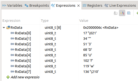
I’ll remind you that we were sending byte data[8] = {0x11, 0x22, 0x33, 0x44, 0x55, 0x66, 0x77, 0x88}; If you look closely, you will see that…
\021 = 0x11
\” = 0x22
3 = 0x33
D = 0x44
U = 0x55
f = 0x66
w = 0x77
\210 = 0x88
That is, we received exactly what we sent, which means our CAN bus is working as expected.