

Blinking an LED STM32
When starting with microcontrollers, the first step is often blinking an LED—essentially the “Hello, World!” of embedded systems. This simple example helps verify that the board is functioning correctly and that the development environment is set up properly. We will program an onboard LED to blink on the STM32F4 Discovery using STM32CubeIDE, while also introducing the basics of working with GPIO (General-Purpose Input/Output). This is the first step toward building more complex projects, such as motor control, sensor integration, or communication interfaces.
A Quick Overview of the STM32F4 Discovery
Let’s briefly discuss the STM32F4 Discovery board, as we will use it frequently in our projects. It is designed to showcase the capabilities of the STM32F4 series and facilitate rapid embedded system development. The board comes equipped with everything needed to get started:
- Built-in ST-Link debugger/programmer
- USB interface
- Buttons and onboard LEDs
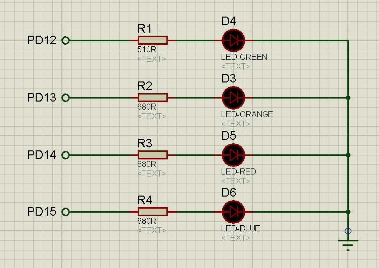
For this project, no additional wiring or soldering is required—everything is already available on the board. The LEDs are connected to PD12 – PD15, and we will use PD12 for blinking.
Creating a Project and Configuring the Clock
Let’s create our project. We covered how to create a project in [this article](link to article 1). Now, let’s configure the clock settings. To do this, go to the RCC tab and select the external oscillator.
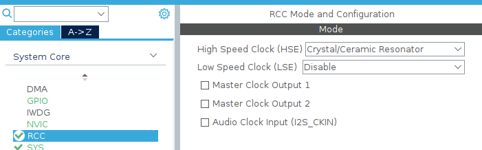
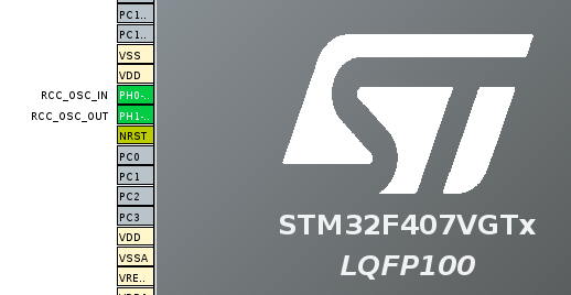
You’ll notice that CubeIDE highlights the RCC_OSC_IN and RCC_OSC_OUT pins in green—these are the oscillator input pins on our microcontroller.
Next, go to Clock Configuration. Since we selected an external oscillator, set the HSE frequency to 8 MHz. ([Full breakdown of Clock Configuration in this article](link to article)). This will result in 16 MHz on the HCLK bus. For our project, this only affects the delay in HAL_Delay(1000);.

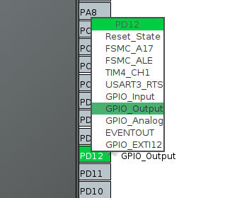
Now, go back to the Pinout & Configuration tab and set up the GPIO. Our goal is to blink LED D4, which is connected to PD12. To do this, click on the pin and select GPIO_Output from the list.
Nothing else needs to be configured. Let’s generate the code for our project.
![]()
Writing the Code
CubeIDE takes care of the initial setup for us. Now, let’s write the code—it’s very simple. The HAL library provides a built-in function for toggling an LED:
HAL_GPIO_TogglePin(GPIOD, GPIO_PIN_12);>// Toggles the LED on PD12</span>
HAL_Delay(500);> // Waits for 500 ms
This function inverts the state of the specified pin:
- If the pin was HIGH (1) → it becomes LOW (0).
- If the pin was LOW (0) → it becomes HIGH (1).
We need to place this code inside the while (1) loop to keep it running continuously:
while(1)
{
/* USER CODE END WHILE */
/* USER CODE BEGIN 3 */
HAL_GPIO_TogglePin(GPIOD, GPIO_PIN_12);
HAL_Delay(500);
}
/* USER CODE END 3 */
Make sure the code is placed strictly between /* USER CODE BEGIN 3 */ and /* USER CODE END 3 */, otherwise, it will be erased when regenerating the project.
Now, let’s build the project by clicking Build.
![]()
We flash our board and see the following: the LED turns on and off.
You can watch the full video on project creation and LED blinking here:
Conclusion and Next Steps
This example demonstrates the basic use of GPIO in STM32, which is a fundamental skill for working with microcontrollers. It is often used for debugging issues in your code.
In the future, we can expand this project by adding button handling, brightness control via PWM, or asynchronous blinking using timers. We’ll cover these topics in upcoming articles.